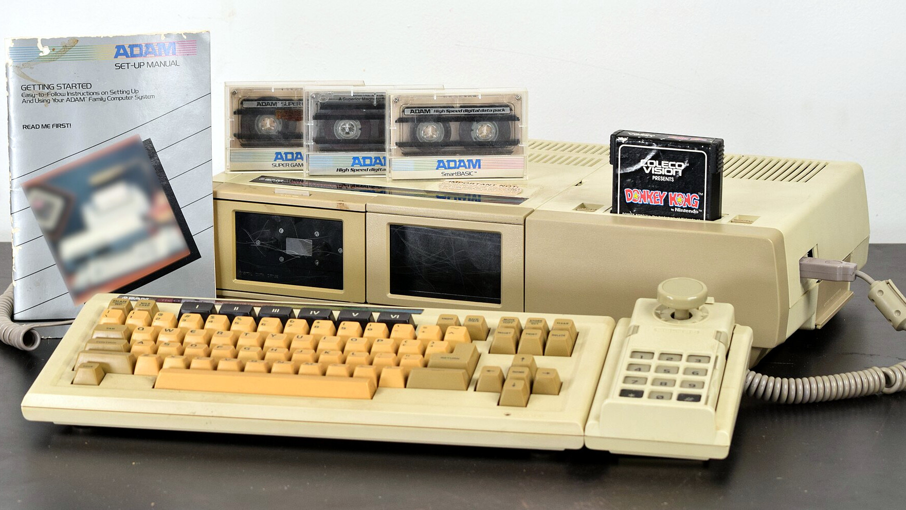
[Neil] from The Cave, a computer and console gaming museum in the UK, has a treat for vintage computing and computer gaming enthusiasts. They received an important piece of game dev history from [Richard Costello], who coded ports of Gauntlet 2, Mortal Kombat, and Primal Rage for Atari ST and Amiga home computers. [Richard] brought them his non-functional Atari Mega ST in the hopes that they could get it working again, and demonstrate to visitors how game development was done back in the 80s — but sadly the hardware is not in the best shape.
That doesn’t stop [Neil], however. The real goal is seeing if it’s possible to re-create the development environment and access the game assets on the SCSI hard drive, and it’s not necessary to revive every part of the hardware to do that. The solution is to back up the drive using a BlueSCSI board which can act as a host, scan the SCSI bus, and dump any device it finds to an SD card. The drive didn’t spin up originally, but some light percussive maintenance solved that.
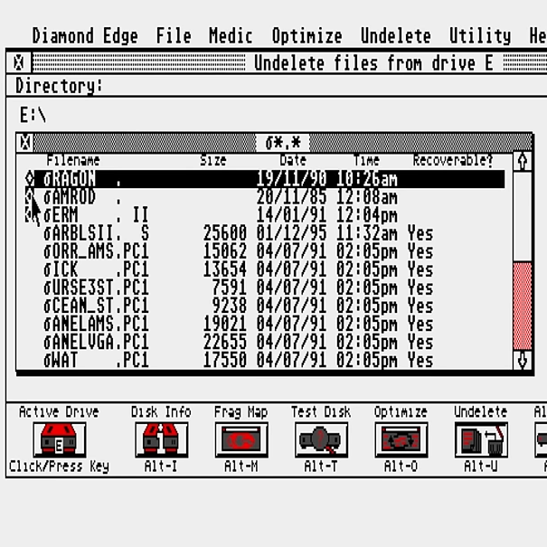
With the files pulled off the drive, it was time to boot it up using an emulator (which begins at the 16:12 mark). There are multiple partitions, but not a lot of files. There was one more trick up [Neil]’s sleeve. Suspecting that deleting everything was the last thing [Richard] did before turning the machine off decades ago, he fired up a file recovery utility. The Atari ST “deleted” files by marking them to be overwritten by replacing the first letter of the filename with a ‘bomb’ character but otherwise leaving contents intact. Lo and behold, directories and files were available to be undeleted!
[Neil] found some fascinating stuff such as mixed game and concept assets as well as what appears to be a copy of Ramrod, a never-released game. It’s an ongoing process, but with any luck, the tools and environment a game developer used in the 80s will be made available for visitors to experience.
Of course, modern retro gaming enthusiasts don’t need to create games the classic way; tools like GB Studio make development much easier. And speaking of hidden cleverness in old games, did you know the original DOOM actually had multi-monitor support hidden under the hood?
Continue reading “Donated Atari Mega ST Gives A Peek At Game Development History”