Automate Away The Drudgery Of CNC Manufacturing

One of the keys to making money with manufacturing is to find something that you can make a lot of. Most small manufacturers have one or two “bread and butter” items that can be cranked out in quantity, which of course has a quality all its own. The problem with that approach, though, is that it runs the risk of being boring. And what better way to avoid that than by automating your high-volume job, with something like this automated  CNC work cell?

Looks like money.

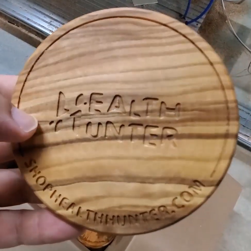
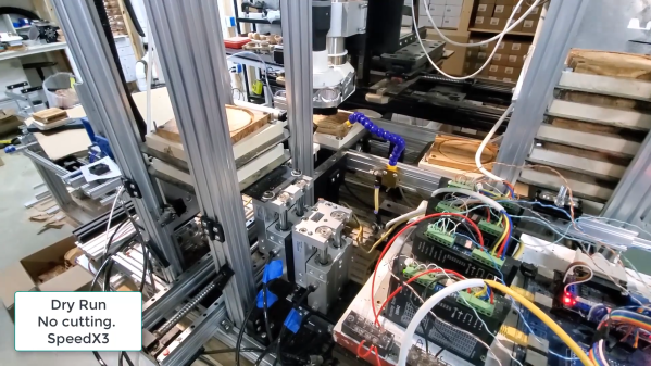
[Maher Lagha] doesn’t offer too much in the way of build details, but the video below pretty much tells the tale. The high-volume items in this case are customized wooden coasters, the kind a restaurant would buy for their bar or a business would give away as swag. The small 3-axis CNC router at the center of the work cell is the perfect choice for making these — one at a time. With no desire to be tied to the machine all day to load raw stock and unload completed coasters, [Maher] came up with automated towers that hold stacks of pallets. Each pallet, which acts as a fixture for the workpiece through multiple operations, moves from the input stack into the router’s work envelope and to the output stack using a combination of servos and pneumatics. The entire work cell is about a meter on a side and contains everything needed for all the operations, including air for the pneumatics and dust extraction.

Each coaster requires two tools to complete — one for surfacing and one for lettering — and [Maher] has two ways to tackle that. The first is to allow a stack of coasters to go through the first operation, change tools, and switch the roughed-in stock back to the input stack for the second round of machining. The other is just to build another work cell dedicated to lettering, which seems to be in progress. In fact, it looks as if there’s a third work cell in the works in [Maher]’s shop. The coaster business must be pretty good.

Continue reading “Automate Away The Drudgery Of CNC Manufacturing”

Learning 3D Printing Best Practices From A Pro

It might seem like 3D printing is a thoroughly modern technology, but the fact is, it’s been used in the industry for decades. The only thing that’s really new is that the printers have become cheap and small enough for folks like us to buy one and plop it on our workbench. So why not take advantage of all that knowledge accumulated by those who’ve been working in the 3D printing field, more accurately referred to as additive manufacturing, since before MakerBot stopped making wooden printers?

That’s why we asked Eric Utley, an applications engineer with Protolabs, to stop by the Hack Chat this week. With over 15 years of experience in additive manufacturing, it’s fair to say he’s seen the technology go through some pretty big changes. Hes worked on everything from the classic stereolithography (SLA) to the newer Multi Jet Fusion (MJF) printers, with a recent focus on printing in metals such as Inconel and aluminum. Compared to the sort of 3D printers he’s worked with, we’re basically playing with hot, semi-melted, LEGOs — but that doesn’t mean some of the lessons he’s learned can’t be applied at the hobbyist level. Continue reading “Learning 3D Printing Best Practices From A Pro”

Wood game piece being carved by a CNC mill with a hacked rotary axis

This $12 CNC Rotary Axis Will Make Your Head Spin

[legolor] brings us a great, cheap rotary axis to add to your small 3 axis CNC mills. How are you going to generate G-Code for this 4th axis? That’s the great part, and the hack, that [legolor] really just swapped the Y axis for the rotation. To finish the workflow and keep things cheap accessible to all there’s a great trick to “unwrap” your 3D model so your CAM software of choice thinks it’s still using a linear Y axis and keeps your existing workflow largely intact. While this requires an extra step in Blender to do the unwrapping, we love the way this hack changes as little of the rest of your process as possible. The Blender script might be useful for many other purposes too.

Wood game pieces carved from wood by a CNC mill with a hacked rotary axis

The results speak for themselves too! We thought the 3D printed parts were suspect in a CNC setup, but for the small scale of game pieces and milling wood, the setup is stable enough to produce a surprisingly accurate and detailed finish. If you want to try the same approach with something larger or a tougher material, [legolor] has a suggestion of a tailstock setup that’s still under $100 USD. Continue reading “This $12 CNC Rotary Axis Will Make Your Head Spin”

CNC Feeds And Speeds, Explained As A First-Timer

If you’ve ever looked into CNC cutting tools, you’ve probably heard the term “feeds and speeds”. It refers to choosing the speed at which to spin the cutting tool, and how fast to plow it into the material being cut. They’re important to get right, and some of the reasons aren’t obvious. This led [Callan Bryant] to share his learned insights as a first-timer. It turns out there are excellent (and somewhat non-intuitive) reasons not to simply guess at the correct values!

A table of variables and how they relate to one another (click to enlarge).

The image above shows a tool damaged by overheating. [Callan] points out that as a novice, one might be inclined to approach a first cutting jobs conservatively, with a low feed rate. But doing this can have an unexpected consequence: a tool that overheats due to spinning too quickly while removing too little material.

CNC cutting creates a lot of heat from friction, and one way to remove that heat is by having the tool produce shavings, which help carry heat away. If a tool is making dust instead of shavings — for example if the feed rate is too conservative — the removed pieces will be too small to carry significant energy, and the tool can overheat.

[Callan] makes a table of variables at work in a CNC system in order to better understand their relationship before getting into making a formula for calculating reasonable feed and speed rates. Of course, such calculations are a reasonable starting point only, and it’s up to the operator to ensure things are happening as they should for any given situation. As our own Elliot Williams observed, CNC milling is a much more manual process than one might think.

Retired Welding Robot Picks Up Side Hustle As CNC Router

Who says you can’t teach an old robot new tricks? Nobody, actually. That saying is about dogs. But it applies to robots too, at least judging by the way this late-90s industrial beast was put to use in a way it was never intended: as a giant CNC router.

The machine in question is an ABB IRB6400, a six-axis, floor-mounted industrial machine that had a long career welding at a Eurorail factory in Austria before [Brian Brocken] made its acquaintance. He procured the non-working machine — no word on what he paid for it — and moved the 2-ton paperweight into his shop, itself a non-trivial endeavor. After a good scrubbing, [Brian] tried to get the machine started up. An error prevented the robot controller from booting; luckily, there’s a large community of ABB users, and [Brian] learned that one of the modules in the controller needed replacement.

After fixing that — and swapping out the controller’s long-dead backup batteries, plus replacing the original 1.44 MB floppy drive with a USB drive — he was able to bring the machine back to life. Unfortunately, the limited amount of internal memory made it difficult to use for anything complicated, so [Brian] came up with an application to stream coordinates to the controller over a serial port, allowing for unlimited operation. With that in place, plus a simple spindle mounted to the robot’s wrist with a 3D printed adapter, [Brian] was able to carve foam blocks into complex shapes. The video below shows everything from delivery to first chips — well, dust at least.

This build seems to be a significant escalation from [Brian]’s previous large-format CNC machine. He must have something interesting in mind, so stay tuned for details.

Continue reading “Retired Welding Robot Picks Up Side Hustle As CNC Router”

Laser And Webcam Team Up For Micron-Resolution Flatness Measurements

When you want to measure the length, breadth, or depth of an object, there are plenty of instruments for the job. You can start with a tape measure, move up to calipers if you need more precision, or maybe even a micrometer if it’s a really critical dimension. But what if you want to know how flat something is? Is there something other than a straightedge and an eyeball for assessing the flatness of a surface?

As it turns out, there is: a $15 webcam and a cheap laser level will do the job, along with some homebrew software and a little bit of patience. At least that’s what [Bryan Howard] came up with to help him assess the flatness of the gantry he fabricated for a large CNC machine he’s working on.

The gantry arm is built from steel tubing, a commodity product with plenty of dimensional variability. To measure the microscopic hills and valleys over the length of the beam, [Bryan] mounted a lens-less webcam to a block of metal. A cheap laser level is set up to skim over the top of the beam and shine across the camera’s image sensor.

On a laptop, images of the beam are converted into an intensity profile whose peak is located by a Gaussian curve fit. The location of the peak on the sensor is recorded at various points along the surface, leading to a map of the microscopic hills and valleys along the beam.

As seen in the video after the break, [Bryan]’s results from such a quick-and-dirty setup are impressive. Despite some wobblies in the laser beam thanks to its auto-leveling mechanism, he was able to scan the entire length of the beam, which looks like it’s more than a meter long, and measure the flatness with a resolution of a couple of microns. Spoiler alert: the beam needs some work. But now [Bryan] knows just where to scrape and shim the surface and by how much, which is a whole lot better than guessing.   Continue reading “Laser And Webcam Team Up For Micron-Resolution Flatness Measurements”

Powercore Aims To Bring The Power Of EDM To Any 3D Printer

The desktop manufacturing revolution has been incredible, unleashing powerful technologies that once were strictly confined to industrial and institutional users. If you doubt that, just look at 3D printing; with a sub-$200 investment, you can start making parts that have never existed before.

Sadly, though, most of this revolution has been geared toward making stuff from one or another type of plastic. Wouldn’t it be great if you could quickly whip up an aluminum part as easily and as cheaply as you can print something in PLA? That day might be at hand thanks to Powercore, a Kickstarter project that aims to bring the power of electric discharge machining (EDM) to the home gamer. The principle of EDM is simple — electric arcs can easily erode metal from a workpiece. EDM machines put that fact to work by putting a tool under CNC control and moving a precisely controlled electric arc around a workpiece to machine complex shapes quickly and cleanly.

Compared to traditional subtractive manufacturing, EDM is a very gentle affair. That’s what makes EDM attractive to the home lab; where the typical metal-capable CNC mill requires huge castings to provide the stiffness needed to contain cutting forces, EDM can use light-duty structures and still turn out precision parts. In fact, Powercore is designed to replace the extruder of a bog-standard 3D printer, and consists almost entirely of parts printed on the very same machine. The video below shows a lot of detail on Powercore, including the very interesting approach to keeping costs down by creating power resistors from PCBs.

While we tend to shy away from flogging crowdfunded projects, this one really seems like it might make a difference to desktop manufacturing and be a real boon to the home lab. It’s also worth noting that this project has roots in the Hackaday community, being based as it is on [Dominik Meffert]’s sinker EDM machine.

Continue reading “Powercore Aims To Bring The Power Of EDM To Any 3D Printer”