Reverse Engineering The Charge Pump Of An 8086 Microprocessor

You’d think that the 8086 microprocessor, a 40-year-old chip with a mere 29,000 transistors on board that kicked off the 16-bit PC revolution, would have no more tales left to tell. But as [Ken Shirriff] discovered, reverse engineering the chip from die photos reveals some hidden depths.

The focus of [Ken]’s exploration of the venerable chip is the charge pump, a circuit that he explains was used to provide a bias voltage across the substrate of the chip. Early chips generally took this -5 volt bias voltage from a pin, which meant designers had to provide a bipolar power supply. To reduce the engineering effort needed to incorporate the 8086 into designs, Intel opted for an on-board charge pump to generate the bias voltage. The circuit consists of a ring oscillator made from a trio of inverters, a pair of transistors, and some diodes to act as check valves. By alternately charging a capacitor and switching its polarity relative to the substrate, the needed -5 volt bias is created.

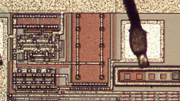
Given the circuit required, it was pretty easy for [Ken] to locate it on the die. The charge pump takes up a relatively huge amount of die space, which speaks to the engineering decisions Intel made when deciding to include it. [Ken] drills down to a very low level on the circuit, with fascinating details on how the MOSFETs were constructed, and why eight transistors were used instead of two diodes. As usual, his die photos are top quality, as are his explanations of what’s going on down inside the silicon.

If you’re somehow just stumbling upon [Ken]’s body of work, you’re in for a real treat. To get you started, you’ll want to check out how he found pi baked into the silicon of the 8087 coprocessor, or perhaps his die-level exploration of different Game Boy audio chips.

Chip Decapping The Easy Way

Chip decapping videos are a staple of the hacking world, and few things compare to the beauty of a silicon die stripped of its protective epoxy and photographed through a good microscope. But the process of actually opening that black resin treasure chest seems elusive, requiring as it does a witch’s brew of solvents and acids.

Or does it? As [Curious Marc] documents in the video below, a little heat and some finesse are all it takes, at least for some chips. The method is demonstrated by [Antoine Bercovici], a paleobotanist who sidelines as a collector of old chips. After removing chips from a PCB — he harvested these chips from an old PlayStation — he uses hot air to soften the epoxy, and then flexes the chip with a couple of pairs of pliers. It’s a bit brutal, but in most of the Sony chips he tried for the video, the epoxy broke cleanly over the die and formed a cleavage plane that allowed the die to be slipped out cleanly. The process is not unlike revealing fossils in sedimentary rocks, a process that he’s familiar with from his day job.

He does warn that certain manufacturers, like Motorola and National, use resins that tend to stick to the die more. It’s also clear that a hairdryer doesn’t deliver enough heat; when they switched to a hot air rework station, the success rate went way up.

The simplicity of this method should open the decapping hobby up to more people. Whether you just want to take pretty pictures or if reverse engineering is on your mind, put the white fuming nitric acid down and grab the heat gun instead.

Continue reading “Chip Decapping The Easy Way”

Forming Sheet Metal Parts With 3D Printed Dies

Using 3D printed forms to bend sheet metal isn’t exactly new. We’ve seen several people create custom dies for their brakes, and the results have shown the concept has merit for small-scale production. But that’s usually where the process ends. A bend here or there is one thing, but the ability to form a complex shape with them has always seemed like asking too much. But judging by his recent experiments, [Shane Wighton] is very close to changing that perception.

The process at work here is, relatively speaking, pretty simple. You print out the upper and lower die, put a piece of sheet metal between them, and then smash them together with a hydraulic press. If everything works correctly, and your CAD skills hold true, the metal will take the desired shape.

Of course, that’s vastly oversimplifying things. As [Shane] explains in the video after the break, there are many nuances to forming sheet metal like this that need to be taken into account, and iteration and experimentation are basically unavoidable. So it’s a good thing you can rapidly redesign and reprint the dies.

Which isn’t to say that the dies themselves didn’t come with their own unique set of challenges. The first ones shattered under the pressure, and it took a few design revisions and eventually a switch to a stronger resin before [Shane] got a set of dies that could form the desired piece. Even still, he’s had a lot of trouble getting the printed parts to survive multiple uses. But he’s confident with some more refinements he could get a repeatable process going, and thinks ultimately producing runs of up to 100 parts on a set of printed dies isn’t out of the question.

Logically, it would seem plastic isn’t an ideal choice for punching and shaping metal. Frankly, it’s not. But if you’re doing in-house manufacturing, the ability to produce complex tooling quickly and easily can help make up for any downsides it might have.

Continue reading “Forming Sheet Metal Parts With 3D Printed Dies”

3D-Printed Tools Turn Bench Vise Into Expedient Press Brake

Chances are pretty good that most of us have used a bench vise to do things far beyond its intended use. That’s understandable, as the vise may be the most powerful hand tool in many shops, capable of exerting tons of pressure with the twist of your wrist. Not taking advantage of that power wouldn’t make any sense, would it?

Still, the clamping power of the vise could sometimes use a little finesse, which is the thinking behind these 3D-printed press brake tools.  [Brauns CNC] came up with these tools, which consist of a punch and a die with mating profiles. Mounted to the jaws of the vise with magnetic flanges, the punch is driven into the die using the vise, forming neat bends in the metal. [Braun] goes into useful detail on punch geometry and managing springback of the workpiece, and handling workpieces wider than the vise jaws. The tools are printed in standard PLA or PETG and are plenty strong, although he does mention using his steel-reinforced 3D-printing method for gooseneck punches and other tools that might need reinforcement. We’d imagine carbon-fiber reinforced filament would add to the strength as well.

To be sure, no matter what tooling you throw at it, a bench vise is a poor substitute for a real press brake. Such machine tools are capable of working sheet metal and other stock into intricate shapes with as few setups as possible, and bring a level of power and precision that can’t be matched by an improvised setup. But the ability to make small bends in lighter materials with homemade tooling and elbow grease is a powerful tool in itself.

Continue reading “3D-Printed Tools Turn Bench Vise Into Expedient Press Brake”

Lead Former Makes LED Cubes A Little Easier To Build

There’s no doubting the allure of a nicely crafted LED cube; likewise, there’s no doubting that they can be a tremendous pain to build. After all, the amount of work scales as the cube of the number of LEDs you want each side to have, and let’s face it – with LED cubes, the bigger, the better. What to do about all that tedious lead forming?

[TylerTimoJ]’s solution is a custom-designed lead-forming tool, and we have to say we’re mighty impressed by it. His LED cubes use discrete RGB LEDs, the kind with four leads, each suspended in space by soldering them to wires. For the neat appearance needed to make such a circuit sculpture work, the leads must be trimmed and bent at just the right angles, a tedious job indeed when done by hand. His tool has servo-controlled jaws that grip the leads, with solenoid-actuated lead formers coming in from below to bend each lead just the right amount. The lead former, along with its companion trimmer, obviously went through a lot of iterations before [TylerTimoJ] got everything right, but we’d say being able to process thousands of LEDs without all the tedium is probably worth the effort.

We’re looking forward to the huge LED cubes this tool will enable. Perhaps this CNC wire bender and an automated wire cutter would come in handy for the supporting wires?

Continue reading “Lead Former Makes LED Cubes A Little Easier To Build”

Punch Those Hole-Drilling Blues Away With A Homebrew Punching Tool

Four times the holes, four times the trouble. With the fate of repetitive motion injury looming due to the need to drill 1,200 holes, [bitluni] took matters into his own hands and built this nifty DIY hole punch for light-gauge sheet metal.

A little backstory will probably help understand why [bitluni] needs so many holes. Back in May, he built a ping pong ball LED video wall for Maker Faire Berlin. That had 300 LEDs and came out great, but at the cost of manually drilling 300 holes in sheet steel with a hand drill. Looking to expand his wall of balls to four times the original size, [bitluni] chose to spend a few days building a punch to make the job more appealing. The business end, with solid bar stock nested inside pieces of tubing, is a great example of how much you can get done without a lathe. The tool is quite complex, with a spring-loaded pilot to help guide the punching operation. When that proved impractical, [bitluni] changed the tool design and added an internal LED to project crosshairs from inside the tool.

The tool itself is mounted into a sturdy welded steel frame that allows him to cover the whole aluminum sheet that will form the panel of his LED wall. It’s pretty impressive metalwork, especially considering this isn’t exactly in his wheelhouse. And best of all, it works – nice, clean holes with no deformation, and it’s fast, too. We’re looking forward to seeing the mega-LED wall when it’s done.

Continue reading “Punch Those Hole-Drilling Blues Away With A Homebrew Punching Tool”

Dice Reader Brings Tech To Your Craps Game… Or, Ya Know, D&D

There are truisms about dice that you’ve probably already heard: if you have just one of them it’s called a “die”, opposite faces of each die always add up to seven, and those dots that you’re adding together are known as “pips”. But what about the infrared properties of those pips? It turns out they reflect less IR than the white body of the die and that trait can be used to build an automatic die reader.

Great projects have a way of bubbling to the surface. The proof of concept comes from way back in 2009, and while the source blog is now defunct, it’s thankfully been preserved by the Internet Archive. In recreating the project based on that barebones description, [Calvin] reached for a set of five IR transmitter/receiver pairs. Take a close look and you’ll see each transmitter is hidden under its partnered receiver. The light shines up through the receiver and the presence of the pip is detected by measuring how much of it bounces back.

This board is only the sensor portion of the design. A 595 shift register provides the ability to control which IR pair is powered, plus five more signals heading out to the analog pins of an Arduino Uno to monitor how much light is being detected by the receivers. Hey, that’s another interesting fact about dice, you only need to read five different pips to establish the value shown!

We wish there were a demo video showing this in action, but alas we couldn’t find one. We were amused to hear [Calvin] mentioned this was a sorting assignment at University and the team didn’t want to build yet another candy sorter. Look, we love an epic M&M sorter just as much as the next electronic geek, but it’s pretty hard to one-up this dice-based random number generator which rolls 1.3 million times each day.