The Word Clock You Can Feel

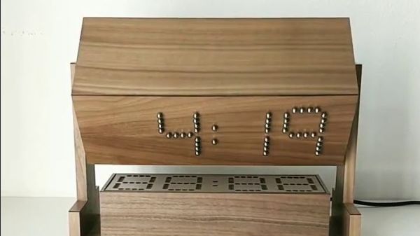
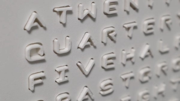
By this point, pretty much everyone has come across a word clock project, if not built one themselves. There’s just an appeal to looking at a clock and seeing the time in a more human form than mere digits on a face. But there are senses beyond sight. Have you ever heard a word clock? Have you ever felt a word clock? These are questions to which Hackaday’s own [Moritz Sivers] can now answer yes, because he’s gone through the extreme learning process involved in designing and building a haptic word clock driven with the power of magnets.

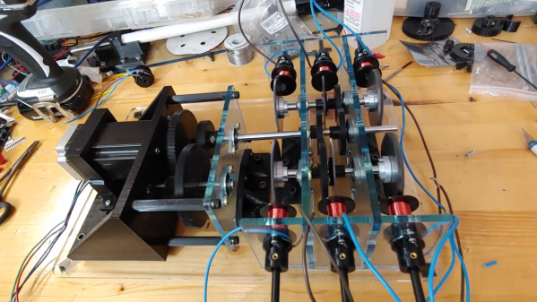
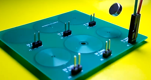
Individual letters of the display are actuated by a matrix of magnetic coils on custom PCBs. These work in a vaguely similar fashion to LED matrices, except they generate magnetic fields that can push or pull on a magnet instead of generating light. As such, there are a variety of different challenges to be tackled: from coil design, to driving the increased power consumption, to even considering how coils interact with their neighbors. Inspired by research on other haptic displays, [Moritz] used ferrous foil to make the magnets latch into place. This way, each letter will stay in its forward or back position without powering the coil to hold it there. Plus the letter remains more stable while nearby coils are activated.

Part of the fun of “ubiquitous” projects like word clocks is seeing how creative hackers can get to make their own creations stand out. Whether it’s a miniaturized version of classic designs or something simple and clean, we  love to see them all. Unsurprisingly, [Moritz] himself has impressed us with his unique take on word clocks in the past. (Editor’s note: that’s nothing compared to his cloud chambers!)

Check out the video below to see this display’s actuation in action. We’re absolutely in love with the satisfying *click* the magnets make as they latch into place.

Continue reading “The Word Clock You Can Feel”

Street-Legalize Your Ebike With A Magnet

Getting into e-biking is a great hobby. It can get people on bikes who might otherwise not be physically able to ride, it can speed up commute times, and it can even make hauling lots of stuff possible and easy, not to mention it’s also fun and rewarding. That being said, there are a wide array of conflicting laws around what your e-bike can and can’t do on the road and if you don’t want to run afoul of the rules you may need a programmable device that ensures your e-bike is restricted in the appropriate way.

This build is specifically for Bafang mid drives, which can be up to 1000 W and easily power a bike beyond the speed limit where [Tomblarom] lives. A small microcontroller is housed in a waterproof box on the bike and wired between the motor’s display and controller. A small hall effect sensor and magnet sit by this microcontroller, and if the magnet is removed then the microcontroller reprograms the bike’s controller to limit the speed and also to disable the throttle, another feature that is illegal in some jurisdictions but not others. As an added bonus, the microcontroller also handles brake lights, turn signals, and automatic headlights for the bike as well.

While the project page mentions removing the magnet while getting pulled over to avoid fines and other punishments, that’s on you. We imagine this could still be useful for someone who wants to comply with local laws when riding on the road, but still wants to remove the restrictions when riding on private property or off-road where the wattage and speed restrictions might not apply.

Tonewheels Warble In This Organ-Inspired Musical Instrument

Younger readers may not recall the days when every mall had a music store — not the kind where tapes and LPs were sold, but the kind where you could buy instruments. These places inevitably had an employee belting out mall-music to all and sundry on an electric organ. And more often than not, the organist was playing a Hammond organ, with the distinct sound of these instruments generated by something similar to this tonewheel organ robot.

Tonewheels are toothed ferromagnetic wheels that are rotated near a pickup coil. This induces a current that can be amplified; alter the tooth profile or change the speed of rotation, and you’ve got control over the sounds produced. While a Hammond organ uses this technique to produce a wide range of sounds, [The Mixed Signal]’s effort is considerably more modest but nonetheless interesting. A stepper motor and a 1:8 ratio 3D-printed gearbox power a pair of shafts which each carry three different tonewheels. The tonewheels themselves are laser-cut from mild steel and range from what look like spur gears to wheels with but a few large lobes. This is a step up from the previous version of this instrument, which used tonewheels 3D-printed from magnetic filament.

Each tonewheel has its own pickup, wound using a coil winder that [TheMixed Signal] previously built. Each coil has a soft iron core, allowing for the addition of one or more neodymium bias magnets, which dramatically alters the tone. The video below shows the build and a demo; skip ahead to 16:10 or so if you just want to hear the instrument play. It’s — interesting. But it’s clearly a work in progress, and we’re eager to see where it goes. Continue reading “Tonewheels Warble In This Organ-Inspired Musical Instrument”

Simple Sensor Makes Filament Measurements A Snap

Just how tight are the manufacturing tolerances of modern FDM printer filament. Inquiring minds want to know, and when such minds are attached to handy fellows like [Thomas Sanladerer], you end up with something like this home-brew filament measurement rig to gather the data you seek.

The heart of this build is not, as one might assume, some exotic laser device to measure the diameter of filament optically. Those exist, but they are expensive bits of kit that are best left to the manufacturers, who use them on their production lines to make sure filament meets their specs. Rather, [Thomas] used a very clever homemade device, which relies on a Hall effect sensor and a magnet on a lever to do the job. The lever is attached to a roller bearing that rides on the filament as it spools through the sensor; variations in diameter are amplified by the lever arm, which wiggles a magnet over the Hall sensor, resulting in a signal proportional to filament diameter.

The full test rig has a motor-driven feed and takeup spools, and three sensors measuring across the filament in three different spots around the radius; the measurements are averaged together to account for any small-scale irregularities. [Thomas] ran several different spools representing different manufacturers and materials through the machine; we won’t spoil the results in the video below, but suffice it to say you probably have little to worry about if you buy from a reputable vendor.

When we see a filament sensor, it’s generally more of the “there/not there” variety to prevent a printer from blindly carrying on once the reel is spent. We’ve seen a few of those before, but this is a neat twist on that concept.

Continue reading “Simple Sensor Makes Filament Measurements A Snap”

Let KiCad And Python Make Your Coils

We like to pretend that our circuits are as perfect as our schematics. But in truth, PCB traces have unwanted resistance, capacitance, and inductance. On the other hand, that means you can use those traces to build components. For example, it isn’t uncommon to see a very small value current sense resistor be nothing more than a long PC board trace. Using PC layers for decoupling capacitance and creating precise transmission lines are other examples. [IndoorGeek] takes us through his process of creating coils on the PCB using KiCad. To help, he used a Python script that works out the circles, something KiCAD has trouble with.

The idea is simple. A coil of wire has inductance even if it is a flat copper trace on a PCB. In this case, the coils are more for the electromagnetic properties, but the same idea applies if you wanted to build tuned circuits. The project took inspiration from FlexAR, an open-source flexible PCB magnet.

Continue reading “Let KiCad And Python Make Your Coils”

Building This Mechanical Digital Clock Took Balls

In the neverending quest for unique ways to display the time, hackers will try just about anything. We’ve seen it all, or at least we thought we had, and then up popped this purely mechanical digital clock that uses nothing but steel balls to display the time. And we absolutely love it!

Click to embiggen (you’ll be glad you did)

One glimpse at the still images or the brief video below shows you exactly how [Eric Nguyen] managed to pull this off. Each segment of the display is made up of four 0.25″ (6.35 mm) steel balls, picked up and held in place by magnets behind the plain wood face of the clock. But the electromechanical complexity needed to accomplish that is the impressive part of the build. Each segment requires two servos, for a whopping 28 units plus one for the colon. Add to that the two heavy-duty servos needed to tilt the head and the four needed to lift the tray holding the steel balls, and the level of complexity is way up there. And yet, [Eric] still managed to make the interior, which is packed with a laser-cut acrylic skeleton, neat and presentable, as well he might since watching the insides work is pretty satisfying.

We love the level of craftsmanship and creativity on this build, congratulations to [Eric] on making his first Arduino build so hard to top. We’ve seen other mechanical digital displays before, but this one is really a work of art.

Continue reading “Building This Mechanical Digital Clock Took Balls”

TMD-1 Makes Turing Machine Concepts Easy To Understand

For something that has been around since the 1930s and is so foundational to computer science, you’d think that the Turing machine, an abstraction for mechanical computation, would be easily understood. Making the abstract concepts easy to understand is what this Turing machine demonstrator aims to do.

The TMD-1 is a project that’s something of a departure from [Michael Gardi]’s usual fare, which has mostly been carefully crafted recreations of artifacts from the early days of computer history, like the Minivac 601  trainer and the DEC H-500 computer lab. The TMD-1 is, rather, a device that makes the principles of a Turing machine more concrete. To represent the concept of the “tape”, [Mike] used eight servo-controlled flip tiles. The “head” of the machine conceptually moves along the tape, its current position indicated by a lighted arrow while reading the status of the cell above it by polling the position of the servo.

Below the tape and head panel is the finite state machine through which the TMD-1 is programmed. [Mike] limited the machine to three states and four transitions three symbols, each of which is programmed by placing 3D-printed tiles on a matrix. Magnets were inserted into cavities during printing; Hall Effect sensors in the PCB below the matrix read the pattern of magnets to determine which tiles are where. The video below shows the TMD-1 counting from 0 to 10, which is enough to demonstrate the basics of Turing machines.

It’s hard not to comment on the irony of a Turing machine being run by an Arduino, but given that [Mike]’s goal was to make abstract concepts easy to understand, it makes perfect sense to leverage the platform rather than try to do this with discrete logic. And you can’t argue with results — TMD-1 made Turing machines clear to us for the first time.

Continue reading “TMD-1 Makes Turing Machine Concepts Easy To Understand”