An image showing a water cooler PCB on the desk, with probes and jumper wires connected to it.

Taking Water Cooler UX Into Your Own Hands With Ghidra

Readers not aware of what Ghidra is might imagine some kind of aftermarket water cooler firmware or mainboard – a usual hacker practice with reflow ovens. What [Robbe Derks] did is no less impressive and inspiring:  A water cooler firmware mod that adds hands-free water dispensing, without requiring any hardware mods or writing an alternative firmware from scratch.

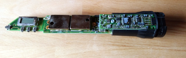
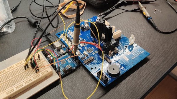
Having disassembled the cooler, [Robbe] found a PIC18F6527 on the mainboard, and surprisingly, it didn’t have firmware readback protection. Even lack of a PICkit didn’t stop him – he just used an Arduino to dump the firmware, with the dumper code shared for us to reuse, and the resulting dumps available in the same repository.

From there, he involved Ghidra to disassemble the code, while documenting the process in a way we can all learn from, and showing off the nifty tricks Ghidra has up its sleeves. Careful planning had to be done to decide which functions to hook and when, where to locate all the extra logic so that there’s no undesirable interference between it and the main firmware, and an extra step taken to decompile the freshly-patched binary to verify that it looks workable before actually flashing the cooler with it.

The end result is a water cooler that works exactly as it ought to have worked, perhaps, if the people defining its user interaction principles were allowed to make it complex enough. We could argue whether this should have been a stock function at all, but either way, it is nice to know that we the hackers still have some of the power to make our appliances friendly — even when they don’t come with an OS. Certainly, every single one of us can think of an appliance long overdue for a usability boost like this. What are your examples?

We’ve covered quite a few Ghidra-involving hacks, but it never feels like we’ve had enough. What about patching an air quality meter to use Fahrenheit? Or another highly educational write-up on cracking GBA games? Perhaps, liberating a Linux-powered 4G router to reconfigure it beyond vendor-defined boundaries? If you have your own goal in mind and are looking to start your firmware reverse-engineering journey, we can say with certainty that you can’t go wrong with our HackadayU course on Ghidra.

Three-Dimensional Design Yields Compact Seven-Segment Hex Displays

Computers, from the simplest to the most complex, aren’t very useful if they can’t provide feedback to a user. Whether that interface takes the form of a monitor, a speaker, or a simple LED, there’s almost always some kind of output. One of the most ubiquitous is the ever-present seven-segment display. They’re small, they’re easy to use, and, perhaps most important, they’re cheap.

While the displays themselves are relatively compact, they often require some sort of driver circuitry — something that translates a digit into voltage at the correct pins. These drivers can take up valuable space, especially on a breadboard, and can sometimes make using seven-segment displays cumbersome. Thankfully, [John Lonergan] has a great solution: driver boards that sit completely beneath the displays. His dual seven-segment hex display project was born out of necessity — he needed it for the breadboard CPU SPAM-1, which was getting a bit too bulky. Each module is two seven-segment displays atop a small PCB. Beneath the displays lives an 8-bit PIC microcontroller, which acts as a driver for both of the displays.

It’s so easy to restrict ourselves to thinking in two dimensions when working on electronic design — even designing multilayer PCBs often feels like working on several, distinct two-dimensional areas rather than one three-dimensional one. The concept of stacking components to save space, while fairly straightforward to implement, is a great example of the kind of problem-solving we love to see here at Hackaday. Of course, if you like the idea of 3D circuit design, you have to check out some of these incredible circuit sculptures we’ve featured in the past.

Continue reading “Three-Dimensional Design Yields Compact Seven-Segment Hex Displays”

Hacking A PIC To Redefine A Microphone’s Transmit Frequency

Software defined radio and widespread software-controlled PLL synthesis for RF has been a game changer. Things like the RTL-SDR can be any kind of radio you like on almost any frequency you like. But not every SDR or PLL system opens the configuration doors to you, the end user. That was the problem [vgnotepad] faced when trying to connect a Sennheiser wireless microphone to some receivers. They didn’t use the same frequencies, even though the transmitter was programmable. The solution to that is obvious — hack the transmitter!

The post is only part one of several parts and if you read to the end, you’ll learn a lot about what’s inside the device and how to crack it. Luckily, the device uses a PIC processor, so getting to the software wasn’t a big issue.

Continue reading “Hacking A PIC To Redefine A Microphone’s Transmit Frequency”

Astronomical Clock Uses Your Spare Clock Motors

We’ll admit we are suckers for clock projects, and the more unusual, the better. We liked the look of [Peter Balch’s] astronomical clock, especially since it was handcrafted and was a relatively simple mechanism. [Peter] admits that it looks like an astronomical clock, but it isn’t the same as a complex instrument from medieval times. Instead, it uses several standard clock motors modified.

We didn’t quite follow some of the explanations for the rotation of the different elements, but the animated GIF cleared it all up. The inner and outer discs are geared at a 6:5 ratio. It takes 2 hours for the inner disc to make one rotation, meaning that every 12 hours the two discs will be back to where they began relative to one another.

Modifying the motors is fine work, requiring a good bit of disassembly and some glue. The electronics that make it tick are quite interesting. To drive the motors, a very specific pulse train is needed, but you also want to conserve battery as much as possible. A simple oscillator with a hex inverter drew more power than desired and an Arduino, even more so. A PIC12F629, though, could sleep a lot and do the job for a very low current consumption. The final clock should run a year on two AA cells.

Hacking A Non-Dimmable LED Fixture

For most of us, the solution to having a non-dimmable LED light bulb but needing a dimmable one is a simple as a drive to the store to get the right kind of bulb. But that seems downright boring, not to mention wasteful, so when [Leo Fernekes] was faced with this problem, he looked for a way to make a non-dimmable bulb dimmable.

To be fair, there was a financial aspect to this hack, too. [Leo] had a bunch of cheap non-dimmable light fixtures he wanted to put to use. He started with a teardown and reverse-engineering of a light strip, which contains little more than LEDs and a small buck converter. His analysis of the circuit led him to a solution for dimming the light: inserting a MOSFET as a shunt around the LEDs. That and the addition of a diode to isolate the LEDs from the current regulator would allow for simple PWM-control of the lights via a microcontroller.

As is typical with these things, there were complications. [Leo] found that a timing problem resulted in flickering LEDs; the fix came from adding a sync circuit that cleverly leveraged a flip-flop inside the PIC16 microcontroller he chose for the circuit. His prototype incorporates these modifications, plus an interface that supports the DALI protocol for architectural lighting control. As always, [Leo] is quick to point out that mixing line voltage into your projects is not without risks, which he takes pains to mitigate. And as is also typical for his projects, [Leo] gives just the right amount of detail to understand the theory behind his design.

Continue reading “Hacking A Non-Dimmable LED Fixture”

Arkanoid Clock Is Exactly What It Sounds Like

A clock can be a simple device that keeps you aware of the current time, but it can also be so much more. It can express an aesthetic ideal from yesteryear, or be a throwback to a popular cultural touchstone. It can even be both, in the case of the brilliant Arkaclock from [Victor Serrano].

The build started when [Victor] wished to create an old-school arcade-style game. Aiming to work with limited hardware, just like the pioneers, he settled on using the PIC18F86K22, with less than 4KB of RAM and just 64KB of program space to play with. Hooked up to a 256 x 64 OLED screen with a pleasant green glow, he set about recreating Arkanoid in assembly language.

With this done, [Victor] noted that the retro-looking display was rather pleasant. At this point, the device was repurposed into a clock, with the program generating an Arkanoid level in the shape of the current time. The AI would then play the game, destroying the bricks each minute before the level changed.

It’s an excellent timepiece, and one that would be perfect for the wall of any indie game studio. Other retro games make for great clocks, too. Video after the break.

Continue reading “Arkanoid Clock Is Exactly What It Sounds Like”

This PIC Is A Squarewave Generator

When we use a microcontroller to flip a few GPIOs or talk SPI to a peripheral chip, we are often overlooking that it will usually contain an array of built-in peripherals that were once the preserve of extra hardware. Analogue ports, timers, UARTs, and clock generators, to name just a few. [Giovanni Bernardo] has been experimenting with one of these, the internal frequency synthesiser on many PIC microcontrollers, and he’s  produced a handy square wave generator for which he’s placed code on GitHub and produced a write-up (Italian language, Google translate link).

The board used is a PIC16F375 Curiosity Nano, and code takes input from a rotary encoder to set the frequency, with a button to select different step sizes and an alphanumeric LCD display to show the current settings. Frequencies from 1 Hz to 15 MHz are possible, with a clever switch between two of the PICs internal clocks to be used as the reference frequency. Stability depends upon whatever source the PIC uses for its own clock, and while we suspect that will be enough for most users it’s not inconceivable that the PIC could be clocked from a GPS-disciplined source or similar were there a requirement for it.

There are plenty of ways to generate square waves from a microcontroller. Most projects use waveform generator ICs.