Most reverse engineering projects we see around here have some sort of practical endpoint in mind. Usually, but not always. Reverse-engineering a 40-year-old cable modem probably serves no practical end, except for the simple pleasure of understanding how 1980s tech worked.
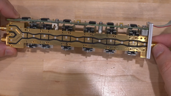
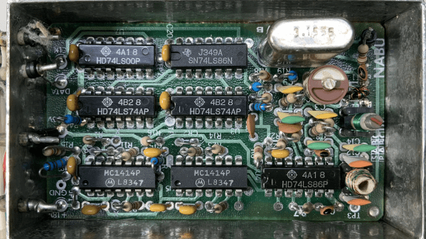
You’ll be forgiven if the NABU Network, the source of the modem [Jared Boone] tears into, sounds unfamiliar; it only existed from 1982 to 1985 and primarily operated in Ottawa, Canada. It’s pretty interesting though, especially the Z80-based computer that was part of the package. The modem itself is a boxy affair bearing all the hallmarks of 1980s tech. [Jared]’s inspection revealed a power supply with a big transformer, a main logic board, and a mysterious shielded section with all the RF circuits, which is the focus of the video below.
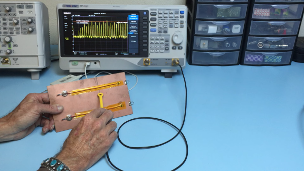
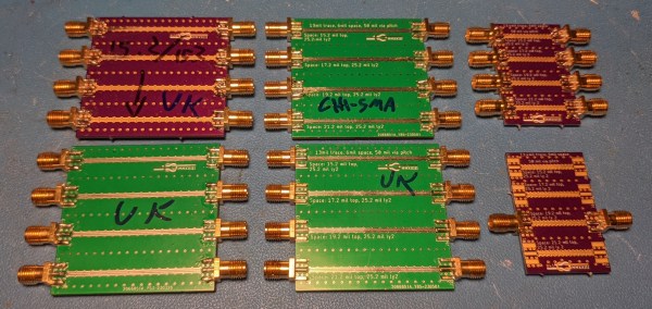
Using a signal generator, a spectrum analyzer, and an oscilloscope, not to mention the PCB silkscreen and component markings, [Jared] built a block diagram of the circuit and determined the important frequencies for things like the local oscillator. He worked through the RF section, discovering what each compartment does, with the most interesting one probably being the quadrature demodulator. But things took a decidedly digital twist in the last compartment, where the modulated RF is turned into digital data with a couple of 7400-series chips, some comparators, and a crystal oscillator.
This tour of 80s tech and the methods [Jared] used to figure out what’s going on in this box were pretty impressive. There’s more to come on this project, including recreating the original signal with SDRs. In the mean time, if this put you in the mood for other videotext systems of the 80s, you might enjoy this Minitel terminal teardown.
Continue reading “Ancient Cable Modem Reveals Its RF Secrets”