Compact Cycloidal Drive Lives Inside This Custom Brushless Motor

With the popularity of robot dogs, many people have gotten on the bandwagon and tried building DIY versions. Most of them end up attaching a gearbox to an off-the-shelf brushless motor and call it a day. Not everyone goes that way, though, which is why this internal cycloidal drive actuator caught our eye.

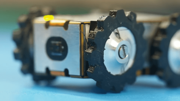
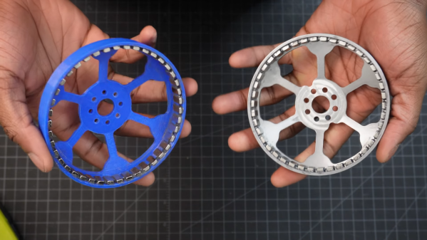
Taking design cues from the MIT Mini Cheetah, [Aaed Musa] approached his actuator from the inside out, literally. His 3D printed cycloidal gearbox is designed to fit inside the stator of a BLDC motor. And not just any BLDC motor, but one built mostly from scratch using a hand-wound — and unwound, and wound again — stator along with a rotor that started as a printed part but was eventually machined from steel. Apart from its fixed ring, the cycloidal drive was mostly 3D printed, with everything fitting nicely inside the stator.

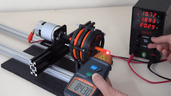
The video below shows the design and assembly process as well as testing of the finished drive. It seems to do really well with speed and positional accuracy, and it delivers a substantial amount of torque. Maybe a little too much, though; testing it with a heavy weight on the end of an arm got the stator coils hot enough to warp the printed parts within. But no matter; this was only a prototype after all. [Aaed] says improvements are in the works, including replacing all the plastic parts with metal ones.

Need a little background on cycloidal drives? They’re pretty cool.

Continue reading “Compact Cycloidal Drive Lives Inside This Custom Brushless Motor”

Magnetic Gearbox, Part 2: Axial Flux Improves Performance

The number of interesting and innovative mechanisms that 3D printing has enabled always fascinates us, and it’s always a treat when one of them shows up in our feeds. This axial flux magnetic gearbox is a great example of such a mechanism, and one that really makes you think about possible applications.

The principles of [Retsetman]’s gearbox are simple for anyone who has ever played with a couple of magnets to understand, since it relies on that powerful attractive and repulsive force you feel when magnets get close to each other. Unlike his previous radial flux gearbox, which used a pair of magnet-studded cylindrical rotors nested one inside the other, this design has a pair of disc-shaped printed rotors that face each other on aligned shafts. Each rotor has slots for sixteen neodymium magnets, which are glued into the slots in specific arrangements of polarity — every other magnet for the low-speed rotor, and groups of four on the high-speed rotor. Between the two rotors is a fixed flux modulator, a stator with ten ferromagnetic inserts screwed into it.

In operation, which the video below demonstrates nicely, the magnetic flux is coupled between the rotors by the steel inserts in the stator so that when one rotor moves, the other moves at a 4:1 (or 1:4) ratio in the opposite direction. [Retsetman] got the gearbox cranked up to about 8,500 RPM briefly, but found that extended operation at as little as 4,000 RPM invited disaster not due to eddy current heating of the inserts or magnets as one might expect, but from simple frictional heating of the rotor bearings.

Torque tests of the original gearbox were unimpressive, but [Retsetman]’s experiments with both laminated stator inserts and more powerful magnets really boosted the output — up to a 250% improvement! We’d also like to see what effect a Hallbach array would have on performance, although we suspect that the proper ratios between the two rotors might be difficult to achieve.

Continue reading “Magnetic Gearbox, Part 2: Axial Flux Improves Performance”

Single Flex PCB Folds Into A Four-Wheel Rover, Complete With Motors

You’ve got to hand it to [Carl Bugeja] — he comes up with some of the most interesting electromechanical designs we’ve seen. His latest project is right up there, too: a single PCB that folds up into a four-wheel motorized rover.

The key to [Carl]’s design lies with his PCB brushless motors, which he has been refining since we first spotted them back in 2018. The idea is to use traces on the PCB for the stator coils to drive a 3D printed rotor containing tiny magnets. They work surprisingly well, even if they don’t generate a huge amount of torque. [Carl]’s flexible PCB design, which incorporates metal stiffeners, is a bit like an unfolded cardboard box, with two pairs of motor coils on each of the side panels. This leaves the other surfaces available for all the electronics, with includes a PIC, a driver chip, and a Hall sensor for each motor, an IMU and proximity sensor for navigation, and an ESP32 to run the show.

With machined aluminum rotors and TPU tires mounted to the folded-up chassis, it was off to the races, albeit slowly. The lack of torque from the motors and the light weight of the rover, along with some unwanted friction due to ill-fitting joints, added up to slow progress, especially on anything other than a dead flat surface. But with some tweaking, [Carl] was able to get the buggy working well enough to call this one a win. Check out the build and testing in the video below.

Knowing [Carl], this isn’t the last we’ll see of the foldable rover. After all, he stuck with his two-wheel PCB motor design and eventually got that running pretty well. We’ll be keeping an eye out for progress on this one.

Continue reading “Single Flex PCB Folds Into A Four-Wheel Rover, Complete With Motors”

Tracking Satellites With A Commodore PET

A recent writeup by Tom Nardi about using the 6502-based NES to track satellites brought back memories of my senior project at Georgia Tech back in the early 80s.  At our club station W4AQL, I had become interested in Amateur Radio satellites.  It was quite a thrill to hear your signal returning from space, adjusting for Doppler as it speeds overhead, keeping the antennas pointed, all while carrying on a brief conversation with other Earth stations or copying spacecraft telemetry, usually in Morse code.

Continue reading “Tracking Satellites With A Commodore PET”

Classic Toy Helicopter Flies Again As DIY Version

For many of us who grew up in the 1970s, “VertiBird”, the fly-it-yourself indoor helicopter, was a toy that was begged for often enough that it eventually appeared under the Christmas tree. And more than a few of the fascinating but delicate toys were defunct by Christmas afternoon, victims of the fatal combination of exuberant play and price-point engineering. But now a DIY version of the classic toy flies again, this time with a more robust design.

To be fair to the designers at Mattel, the toy company that marketed VertiBird, the toy was pretty amazing. The plastic helicopter was powered by a motor located in the central base, which rotated a drive rod that ran through a stiff tether. Small springs in the base and at the copter acted as universal joints to transmit power to the rotor. These springs were the weak point in the design, especially the one in the base, often snapping in two.

[Luke J. Barker]’s redesign puts a tiny gear motor in the aircraft rather than in the base, something that wouldn’t have been feasible in the original. To address the problem of getting electrical power from the base to the aircraft, [Luke] eschewed an expensive slip ring and instead used a standard 3.5-mm audio jack and plug. The plug serves as an axle for the main gear in the base that powers the copter’s rotation; sadly, this version doesn’t tilt the aircraft mechanically to control backward and forward flight like the original. A pair of pots with 3D-printed levers control throttle and flight direction through an Arduino; see it in action in the video below.

These pages abound with rotorcraft builds, both helicopters and multirotor. We appreciate all manner of flying machines, but this one really takes us back.

Continue reading “Classic Toy Helicopter Flies Again As DIY Version”

Jigsaw Motor Uses PCB Coils For Radial Flux

Electric motors are easy to make; remember those experiments with wire-wrapped nails? But what’s easy to make is often hard to engineer, and making a motor that’s small, light, and powerful can be difficult. [Carl Bugeja] however is not one to back down from a challenge, and his tiny “jigsaw” PCB motor is the latest result of his motor-building experiments.

We’re used to seeing brushless PCB motors from [Carl], but mainly of the axial-flux variety, wherein the stator coils are arranged so their magnetic lines of force are parallel to the motor’s shaft – his tiny PCB motors are a great example of this geometry. While those can be completely printed, they’re far from optimal. So, [Carl] started looking at ways to make a radial-flux PCB motor. His design has six six-layer PCB coils soldered perpendicular to a hexagonal end plate. The end plate has traces to connect the coils in a star configuration, and together with a matching top plate, they provide support for tiny bearings. The rotor meanwhile is a 3D-printed cube with press-fit neodymium magnets. Check out the build in the video below.

Connected to an ESC, the motor works decently, but not spectacularly. [Carl] admits that more tweaking is in order, and we have little doubt he’ll keep optimizing the design. We like the look of this, and we’re keen to see it improved.

Continue reading “Jigsaw Motor Uses PCB Coils For Radial Flux”

Magnetic Bearings Might Keep This Motor Spinning For Millennia

We see our share of pitches for perpetual motion machines in the Hackaday tips line, and we generally ignore them and move along. And while this magnetic levitation motor does not break the laws of thermodynamics, it can be considered a perpetual motion machine, at least for certain values of perpetuity.

The motor that [lasersaber] presents in the video below is unconventional, to say the least. It’s not a motor that can do any useful work, spinning at a stately pace beneath its bell-jar enclosure as it does. The design is an extension of [lasersaber]’s “EZ-Spin” motor, which we’ve featured before, and has the same basic layout – a ring of coils wired in series forms the stator, while a disc bearing permanent magnets forms the rotor. The coils, scavenged from those dancing flowerpot solar ornaments, are briefly energized by the rotor passing over a reed switch, giving the rotor a little boost.

The difference here is that rather than low-friction sapphire bearings, this motor uses zero-friction magnetic levitation using pyrolyzed graphite discs. The diamagnetic material hovers above a rare-earth ring magnet, supporting a slender vertical shaft that holds the rotor and another magnetic bearing at the top. It’s fussy to adjust, but once it’s stable, the only friction in the system should be the drag caused by air in the bell jar. [lasersaber]’s current measurements of the motor running at slow speed are hard to believe – 150 nanoamps – leading to an equally jaw-dropping calculated run-time on a single AA battery of 89 millennia.

[lasersaber] is the first to admit that he’s not confident with his measurements, but it seems clear that his motor will likely outlive any chemical battery used to power it. Whatever the numbers are, we like the styling of the thing, and the magnetic bearings are cool too.

Continue reading “Magnetic Bearings Might Keep This Motor Spinning For Millennia”