Wired Networking For The ESP8266

The ever popular ESP8266 is popping up in more and more projects. There are CNC controllers, blinkey WiFi lighting, and downright bizarre WiFi to Ethernet bridges. [Cicero] has thrown his hat into the ring with one of these Ethernet-enabled ESP8266 builds, and right now everything works, it’s simple to put together, and cheap to build.

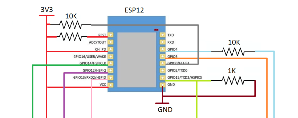
Astute readers will notice we’ve seen something like this before. A few months ago, [cnlohr] discovered the Ethernet controller in the ESP8266. This was, by every account, the hard way of doing things. [cnlohr] was driving the Ethernet directly through the ESP’s I2S bus. [Cicero]’s project does not. It uses the cheap ENC28J60 SPI to Ethernet adapter to put the ESP on a wired network. Is one solution better than the other? That’s arguable. Is one solution much simpler than the other? Yes, [Cicero]’s work allows anyone to add Ethernet to the ESP8266 with a few resistors and a module that costs $3 from the usual online shops.

With the Ethernet stack taken from [Ulrich Radig], the SPI driver from [MetalPhreak], and an ESP8266-based web server from [Sprite_tm], [Cicero] managed to serve up web pages through both the wired and wireless connections.

Although this build is not as technically amazeballs as [cnlohr]’s work with driving Ethernet directly from the ESP, it is very easy to implement, opening up the doors to a few of the more interesting capabilities of a wired ESP. With the Ethernet unlocked, there’s a free WiFi interface to wardrive, snoop around in promiscuous mode, inject packets, bridge a bunch of ESPs in mesh mode to another network, and other network shenanigans. The ENC28J60 modules have probably already found their way into a few parts bins and junk boxes already, making [Cicero]’s work the quick start guide to wired networking on the ESP.

Thanks [PuceBaboon] for sending this one in.

Interactive WeddingBots Built Into Nespresso Capsules

Today is a very special day for [Mandy and Sebastian], as they conclude the sacred solder joint of marriage. We send our sincerest congratulations and best wishes to the bridal couple, and can’t help but envy the guests of their ceremony, who received a very special wedding favor: A WeddingBot.

img_3337For their wedding party, [Mandy and Sebastian] created a little game on their own (translated). Each guest would receive a unique, little WeddingBot. Each of these is individually tailored for a certain guest and features a fitting look, a characteristic behavior and would play a special melody or jingle meaningful to this guest. However, the guests don’t get their WeddingBot, they get the WeddingBot of another guest – and the challenge to find this guest on the party. Guests would then exchange their WeddingBots, which also makes a great occasion to introduce themselves to each other. If the clues given by the WeddingBots themselves would not suffice to find the right owner, guest could place a WeddingBot on a clue station, which then would provide further hints by displaying images, texts or even riddles.

The design is based on the ATtiny45 microcontroller, with LEDs for the eyes, a light sensor, and a piezo disc for the sound as the main components. As an enclosure, they chose to repurpose empty Nespresso® capsules, which look nice and adds volume to the PCBs. The smiley face silk screen on the PCBs was then individualized with a black marker and packed in a beautiful hand-crafted box. The little fellows communicate with the Raspberry Pi based clue station by flashing their LEDs in a certain pattern. A light sensor hooked up to the Pi lets the station identify the bot and display the corresponding clue on a screen. Check out the video below to see how it works:

Continue reading “Interactive WeddingBots Built Into Nespresso Capsules”

What Could Go Wrong: SPI

Serial Peripheral Interface (SPI) is not really a protocol, but more of a general idea. It’s the bare-minimum way to transfer a lot of data between two chips as quickly as possible, and for that reason alone, it’s one of my favorites. But that doesn’t mean that everything is hugs and daffodils. Even despite SPI’s simplicity, there are still a few ways that things can go wrong.

In the previous article in this series, inspired by actual reader questions, I looked into troubleshooting asynchronous serial connections. Now that you’ve got that working, it’s time to step up to debugging your SPI bus! After a brief overview of the system, we’ll get into how to diagnose SPI, and how to fix it.

Continue reading “What Could Go Wrong: SPI”

SpotMini Struts Its Stuff

Boston Dynamics, the lauded robotics company famed for its ‘Big Dog’ robot and other machines which push mechanical dexterity to impressive limits have produced a smaller version of their ‘Spot’ robot dubbed ‘SpotMini’.

A lightweight at 55-65 lbs, this quiet, all-electric robot lasts 90 minutes on a full charge and boasts partial autonomy — notably in navigation thanks to proprioception sensors in the limbs. SpotMini’s most striking features are its sleek new profile and manipulator arm, showing off this huge upgrade by loading a glass into a dishwasher and taking out some recycling.

Robots are prone to failure, however, so it’s good to know that our future overlords are just as susceptible to slipping on banana peels as we humans are.

Continue reading “SpotMini Struts Its Stuff”

HALT In The Name Of Testing

“Did I forget something?” It’s that nagging feeling every engineer has when their project is about to be deployed – it may be a product about to be ramped into production, a low volume product, or even a one off like a microsatellite. If you have the time and a few prototypes to spare though, there are ways to alleviate these worries. The key is a test method which has been used in aerospace, military, and other industries for years – Highly Accelerated Life Testing (HALT).

How to HALT

The idea behind HALT testing can be summed up in a couple of sentences:

  • Beat your product to death.
  • Figure out what broke.
  • Fix it, and fix the design.
  • Repeat.

Sounds barbaric, and in many cases it is. HALT testing is often associated with giant test chambers which are literally designed to torture anything inside them. Liquid nitrogen shock cools the chamber as low as -100°C. The Device Under Test (DUT) can soak at that temperature for hours. Powerful heaters then blast the chamber, causing temperature rises of up to 90°C per minute, topping off at up to 200°C. Pneumatic hammers beat on the chamber table causing vibrations at up to 90 Grms and 10 KHz. Corrosive sprays simulate years of rain and humidity. These chambers are literally hell on earth for any device unlucky enough to be placed inside them. It’s easy to see why this sort of testing is often referred to as “Shake and Bake”.

Continue reading “HALT In The Name Of Testing”

Bridging The Air Gap; Data Transfer Via Fan Noise

When you want to protect a computer connected to the Internet against attackers, you usually put it behind a firewall. The firewall controls access to the protected computer. However, you can defeat any lock and there are ways a dedicated attacker can compromise a firewall. Really critical data is often placed on a computer that is “air gapped.” That is, the computer isn’t connected at all to an insecure network.

An air gap turns a network security problem into a physical security problem. Even if you can infect the target system and collect data, you don’t have an easy way to get the data out of the secure facility unless you are physically present and doing something obvious (like reading from the screen into a phone). Right? Maybe not.

Researchers in Isreal have been devising various ways to transmit data from air walled computers. Their latest approach? Transmit data via changing the speed of cooling fans in the target computer. Software running on a cellphone (or other computer, obviously) can decode the data and exfiltrate it. You can see a video on the process below.

Continue reading “Bridging The Air Gap; Data Transfer Via Fan Noise”

1024 “Pixel” Sound Camera Treats Eyes To Real-Time Audio

A few years ago, [Artem] learned about ways to focus sound in an issue of Popular Mechanics. If sound can be focused, he reasoned, it could be focused onto a plane of microphones. Get enough microphones, and you have a ‘sound camera’, with each microphone a single pixel.

Movies and TV shows about comic books are now the height of culture, so a device using an array of microphones to produce an image isn’t an interesting demonstration of FFT, signal processing, and high-speed electronic design. It’s a Daredevil camera, and it’s one of the greatest builds we’ve ever seen.

[Artem]’s build log isn’t a step-by-step process on how to make a sound camera. Instead, he went through the entire process of building this array of microphones, and like all amazing builds the first step never works. The first prototype was based on a flatbed scanner camera, simply a flatbed scanner in a lightproof box with a pinhole. The idea was, by scanning a microphone back and forth, using the pinhole as a ‘lens’, [Artem] could detect where a sound was coming from. He pulled out his scanner, a signal generator, and ran the experiment. It didn’t work. The box was not soundproof, the inner chamber should have been anechoic, and even if it worked, this camera would only be able to produce an image or two a minute.

back
8×8 microphone array (mics on opposite side) connected to Altera FPGA at the center

The idea sat in the shelf of [Artem]’s mind for a while, and along the way he learned about FFT and how the gigantic Duga over the horizon radar actually worked. Math was the answer, and by using FFT to transform a microphones signals from up-and-down to buckets of frequency and intensity, he could build this camera.

That was the theory, anyway. Practicality has a way of getting in the way, and to build this gigantic sound camera he would need dozens of microphones, dozens of amplifiers, and a controller with enough analog pins, DACs, and processing power to make sense of all of this.

This complexity collapsed when [Artem] realized there was an off-the-shelf part that was a perfect microphone camera pixel. MEMS microphones, like the kind found in smartphones, take analog sound and turn it into a digital signal. Feed this into a fast enough microcontroller, and you can perform FFT on the signal and repeat the same process on the next pixel. This was the answer, and the only thing left to do was to build a board with an array of microphones.

4x4
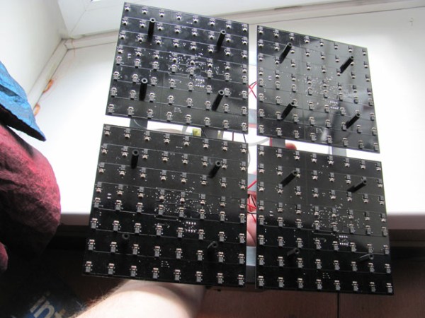
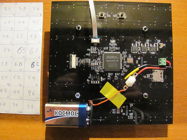
[Artem]’s camera microphone is constructed out of several modules, each of them consisting of an 8×8 array of MEMS microphones, controlled via FPGA. These individual modules can be chained together, and the ‘big build’ is a 32×32 array. After a few problems with manufacturing, the board actually worked. He was recording 64 channels of audio from a single panel. Turning on the FFT visualization and pointing it at a speaker revealed that yes, he had indeed made a sound camera.
The result is a terribly crude movie with blobs of color, but that’s the reality of a camera that only has 32×32 resolution. Right now the sound camera works, the images are crude, and [Artem] has a few ideas of where to go next. A cheap PC is fast enough to record and process all the data, but now it’s an issue of bandwidth; 30 sounds per second is a total of 64 Mbps of data. That’s doable, but it would need another FPGA implementation.

Is this sonic vision? Yes, technically the board works. No, in that the project is stalled, and it’s expensive by any electronic hobbyist standards. Still, it’s one of the best to grace our front page.

[Thanks zakqwy for the tip!]