Finding RF Cable Impedance

At DC and low frequency, we can pretend wires are perfect conductors. At radio frequencies, though, there are many effects that you need to take into account for wires and cables. One of these is characteristic impedance. If you have a marked cable, you can look it up on the Internet, of course. But what if you don’t know what kind of wire it is? With help from [The Offset Volt], you can measure it as he shows in the video below.

This is one of those things that used to take exotic test equipment like an LCR bridge, but these days meters that measure inductance and capacitance are commonplace. The trick is simple: measure the capacitance and then short one end of the cable and measure the inductance.

Continue reading “Finding RF Cable Impedance”

Arduband Gives Your Eyes A Hand

Let’s face it, we probably all sit at our computers for way too long without getting up. Yes, there’s work to be done, games to be played, and the internet abounds with people who are wrong and must be down-voted and/or corrected. We totally get and respect all that. However, if you want to maintain your middle- and long-range vision, you should really get up regularly and gaze out the window for a bit.

In fact, the Arduband does you one better. Its Arduino Nano and accelerometer check your position every ten minutes. If you haven’t changed your Z by the third check, then it’s time for a break. The combination of an RGB LED, buzzer, and vibrating disc motor working together should be enough to pull you out of any computerized stupor, and they won’t give up and go back to sleep until you have stood up and remained upright for one minute.

We like that [ardutronics123] spun up a board and made it small enough to be wrist-mounted using a watch strap. It would work just as well worn around your neck, and would probably even fit in your pocket. Blink a few times before you check out the build video after the break.

Arduband would be great on the go, but who does that anymore? If you spend every day at the same desk, you could point a time-of-flight sensor at your chair and start a timer.

Continue reading “Arduband Gives Your Eyes A Hand”

DMCA Takedown Issued Over Casio Code That Wasn’t

Earlier this month, we posted coverage of an ingenious calculator hack that took a Casio calculator and put an ESP8266 module and an OLED display in the space occupied by its solar cell. Controlled by a pair of unobtrusive Hall effect devices, the calculator could have been used as an ingenious cheating device but was to us the epitome of a well-executed hack. We may have liked it but it seems the folks at Casio didn’t, because they’ve issued a DMCA takedown notice for the project’s GitHub repository.

Editor’s Update: [Tom Fleet] reports that GitHub has completed the DMCA review and found the code repo does not infringe on Casio’s IP. However, it appears the copyright claim on the YouTube video has not been resolved and that video remains unavailable. However, that video is still available on the Internet Archive.

This is a picture of Barbra Streisand, who might almost be the patron saint of unintended consequences. Unknown author / Public domain
This is a picture of Barbra Streisand, who might almost be the patron saint of unintended consequences. Unknown author / Public domain.

We’re not lawyers, but if you’d care to visit our original coverage and watch the video in full, you’ll see that the ESP does not in any way tap into the calculator’s functions. The epoxy blob over the Casio processor is intact and no wires connect to the calculator mainboard, so it is difficult to imagine how any Casio code could have found its way into a repository full of ESP8266 code for the Arduino IDE. A quick search for “Hack-Casio-Calculator” on GitHub, at the time of publishing, turned up the relevant code despite Casio’s takedown, and we can’t see what they’re on about. Maybe you can?

Over the years there have been many attempts to use the DMCA on projects in our community. Some have been legitimate, others have been attempts to suppress exposure of woeful security, and still more have been laughably absurd. This one seems to us to edge into the final category, because it is difficult to see how the project described could contain any Casio code at all. It would be entirely legitimate to  issue a DMCA takedown had the epoxy blob been removed and Casio’s code been retrieved from the calculator chip (and we’d certainly cover that story!), but as far as we can see taking a scalpel to a calculator’s case and stuffing a module behind the solar panel window does not come close.

It’s evident that Casio do not like the idea of one of their calculators being turned into a cheating device, and we understand why that might be the case. But to take the DMCA route has served only to bring more publicity to the affair, and those of us with long memories know that this can only lead to one conclusion.

Thanks [Tom] and others for the tip.

Matrix Of Resistors Forms The Hot Hands Behind This Thermochromic Analog Clock

If you’re going to ditch work, you might as well go big. A 1,024-pixel thermochromic analog clock is probably on the high side of what most people would try, but apparently [Daniel Valuch] really didn’t want to go to work that day.

The idea here is simple: heat up a resistor by putting some current through it, lay a bit of thermochromic film over it, and you’ve got one pixel. The next part was not so simple: expanding that single pixel to a 32 by 32 matrix.

To make each pixel square-ish, [Daniel] chose to pair up the 220-ohm SMD resistors for a whopping 2,048 components. Adding to the complexity was the choice to drive them with a 1,024-bit shift register made from discrete 74LVC1G175 flip flops. With the Arduino Nano and all the other support components, that’s over 3,000 devices with the potential to draw 50 amps, were someone to be foolish or unlucky enough to turn on every pixel at once. Luckily, [Daniel] chose to emulate an analog clock here; that led to additional problems, like dealing with cool-down lag in the thermochromic film when animating the hands, which had to be dealt with in software.

We’ve seen other thermochromic displays before, including recently with this temperature and humidity display. This one may not be the highest resolution display out there, but it’s big and bold and slightly dangerous, and that makes it a win in our book.

Flexible PCB Earrings Put The Art In Art Deco

Earrings have been a hackers’ target for electronic attachment for quite a while, but combining the needed components into a package small enough to wear in that finicky location is quite a challenge. If [Sawaiz Syed]’s Art Deco Earrings are anything to go by, ear computers have a bright future ahead of them!

This is a project unusually well described by its name. It is in fact an earring, with art deco styling. But that sells it way too short. This sliver of a flex circuit board is double sided to host an ATtiny, accelerometer, LDO, and eight 2020 formfactor controller-integrated LEDs. Of course it’s motion sensitive, reacting to the wearer’s movement via LED pattern. [Sawaiz] makes reference to wearing it while dancing, and we can’t help but imagine an entire ballroom all aglow with tiny points of LED light.

The Art Deco Earrings are also set apart by the thoroughness of their documentation (have we mentioned how much we love detailed documentation?). [Sawaiz] not only drops the source in your lap, but the README in the Github repo linked at the top walks the reader through each component of the design in detail. Plus the PCBA render is so complete it includes a model of the wire loop to fit through the wearer’s ear; how cool is that? The single piece that’s still in progress is the battery. The earring itself hosts an LDO, so all that is required is stashing a battery somewhere discrete, perhaps in the user’s hair? We’re looking forward to seeing what [Sawaiz] works out.

For the full effect, check out the gif of an assembled unit in action after the break.

Continue reading “Flexible PCB Earrings Put The Art In Art Deco”

Conduit, Birdhouse, And Skateboard Become Giant Pen Plotter

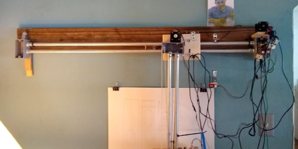
If you think you need fancy parts to build a giant robot drawing machine, think again! [Cory Collins] shows you how he built his Big-Ass Wall Plotter v.2 out of stuff around the house or the hardware store, including electrical conduit, gang boxes, scrap wood, and skateboard bearings, alongside the necessary stepper motors, drivers, and timing belt. (You should consider having this trio of parts on hand as well, in our opinion.) With a span of 48″ (1.2 m) on a side, you probably don’t have paper that’s this big.

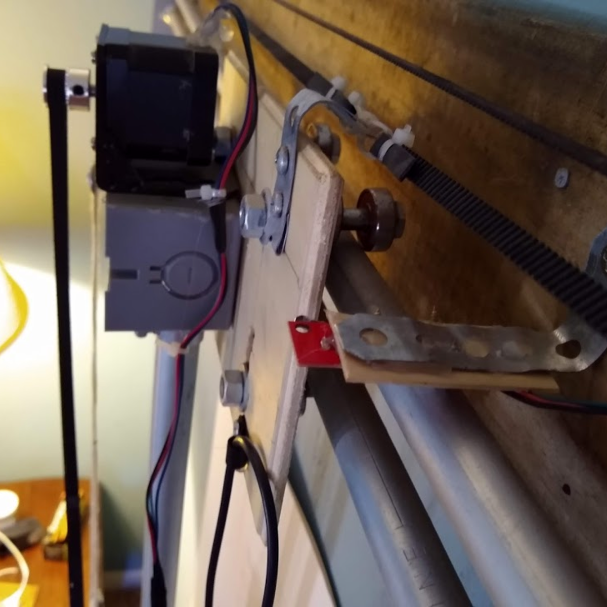
And while the construction is definitely rough-and-ready, there are a ton of details that turn this pile of parts into a beautifully working machine in short order. For instance, making the rails out of electrical conduit has a few advantages. Of course it’s cheap and strong, but the availability of off-the-shelf flanges makes assembly and disassembly easy. It also hangs neatly on the wall courtesy of some rubber cuphooks.

Note also the use of zip-tie belt tensioners: a simple and effective solution that we heartily endorse. [Corey] makes good use of custom 3D printed parts where they matter, like the compliant pen holder and linear mechanism for the z-axis, but most of the mechanical accuracy is courtesy of wooden shims and metal strapping.

[Corey] uses the machine to make patterns for his paper sculptures that are worth a look in their own right, and you can see the machine in action, sped up significantly, in the video below. This is the perfect project if you have a DIY eggbot that’s out of commission post-Easter: it reuses all the same parts, just on a vastly different scale. Heck, [Corey] even uses the same Inkscape Gcodetools extension as we did in that project. Now you know what we’re up to this weekend.

Can’t get enough pen plotters? Check out this one that lets you write whatever you want!

Continue reading “Conduit, Birdhouse, And Skateboard Become Giant Pen Plotter”

Resistors Sorter Measures Values

We’ve all been there. A big bag of resistors all mixed up. Maybe you bought them cheap. Maybe your neatly organized drawers spilled. Of course, you can excruciatingly read the color codes one by one. Or use a meter. But either way, it is a tedious job. [Ishann’s] solution was to build an automatic sorter that directly measures the value using a voltage divider, rather than rely on machine vision as is often the case in these projects. That means it could be modified to do matching for precise circuits (e.g., sort out resistors all marked 1K that are more than a half-percent away from one nominal value).

There is a funnel that admits one resistor at a time into a test area where it is measured. A plate at the bottom rotates depending on the measured value. In the current implementation, the resistor either falls to the left or the right. It wouldn’t be hard to make a rotating tray with compartments for different values of resistance. It looks like you have to feed the machine one resistor at a time, and automating that sounds like a trick considering how jumbled loose axial components can be. Still, its a fun project that you probably have all the parts to make.

An Arduino powers the thing. An LCD screen and display control the action. If you want some practice handling material robotically, this is a great use of servos and gravity and it does serve a practical purpose.

We have seen many variations on this, including ones that read the color code. If you ever wanted to know where the color code for resistors came from, we took a trip to the past to find out earlier this year.

Continue reading “Resistors Sorter Measures Values”