What’s In A Raspberry Pi Processor Update?

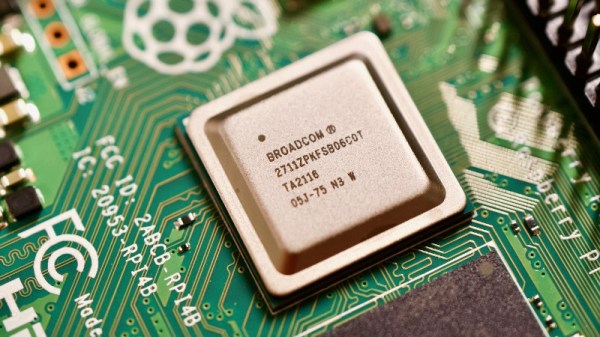
Those of us who have followed the Raspberry Pi over the years will be familiar with the various revisions of the little board, with their consequent new processors. What may be less obvious is that within the lifetime of any chip there will often be minor version changes, usually to fix bugs or to fine-tune production processes. They’re the same chip, but sometimes with a few extra capabilities. [Jeff Geerling] didn’t miss this when the Raspberry Pi 400 had a BCM2711 with a newer version number than that on the Pi 4, and now he’s notices the same chip on Pi 4 boards.

Why might they run two different revisions of the chip in parallel? It seems that the update changes the amount of memory addressable by the eMMC and the PCIe bus, the former could only see the first 1GB and the latter the first 3Gb. For the lower-spec Pi 4 boards this doesn’t present a problem, but for those with 8 gigabytes of memory it could clearly be an issue. Thus the Pi 400 and the top spec Pi 4 now have a newer BCM2711 version. This will almost certainly pass unnoticed for the average Raspberry Pi OS user, but the extra memory addressing space should be of interest for hardware experimenters wishing to expose that PCIe bus and talk to peripherals such as a GPU. That said, though he suggests the Compute Module 4  has the newer revision, his own experiments were unsuccessful.

[Editor’s Note: our own overclocking experiments show the C-version SOCs to run cooler/faster than their B counterparts, so it’s nice to have the better chips in the “normal” Pi form factor and not just the Pi 400 and compute modules.]

an image of the graffomat at work

Automate Your Graffiti With The Graffomat!

In Banksy’s book, Wall and Piece, there is a very interesting quote; “Imagine a city where graffiti wasn’t illegal, a city where everybody could draw whatever they liked…”. This sounds like it would be a very exciting city to live in, except for those of us who do not have an artistic bone in their body. Luckily, [Niklas Roy] has come up with the solution to this problem; the Graffomat, a spray can plotter.

The Graffomat is, in its creator’s own words, a “quick and dirty graffiti plotter.” It is constructed primarily from wood and driven by recycled cordless drills that pulls string pulleys to move the gantry.  The Arduino Nano at the heart of the Graffomat can be controlled by sending coordinates over serial. This allows for the connection of an SD card reader to drip-feed the machine, or a computer to enable real-time local or over-the-internet control.

We are especially impressed with how [Niklas] handled positional tracking. The cordless drills were certainly not repeatable like a stepper motor, as to allow for open-loop control. Therefore, the position of the gantry and head needed to be actively tracked. To achieve this, the axes are covered with black and white striped encoder strips, that is then read by a pair of phototransistors as the machine moves along. These can then be paired with the homing switches in the top left corner to determine absolute position.

Graffomat is not the first automated graffiti machine we’ve covered. Read here about the robot that painted murals by climbing smokestacks in Estonia. 

Continue reading “Automate Your Graffiti With The Graffomat!”

A conventiongoer plays Pokemon on a working Color Game Boy costume.

Convention Plays Pokemon On Giant Color Game Boy Costume

Standard cosplay is fun and all, but what is there for admirers to do but look you up and down and nitpick the details? Interactive cosplay, now that’s where it’s at. [Jaryd Giesen] knows this, and managed to pull together a working color Game Boy costume in a few days.

The original plan was to use a small projector on an arm, like one of those worm lights that helped you see the screen, but [Jaryd] ended up getting a secondhand monitor and strapping it to his chest. Then he took the rest of the build from there. Things are pretty simple underneath all that cardboard: there’s a Raspberry Pi running the RetroPie emulator, a Pico to handle the inputs, and two batteries — one beefy 12,000 mAH battery for the monitor, and a regular power pack for the Pi and the Pico.

As you’ll see in the build and demo video after the break, nearly 100 people stopped to push [Jaryd]’s buttons. They didn’t get very far in the game, but it sure looks like they had fun trying.

Since we’re still in a pandemic, you may want to consider incorporating a mask into your Halloween costume this year. Just a thought.

Continue reading “Convention Plays Pokemon On Giant Color Game Boy Costume”

Shortwave Radio Picks Up Sideband

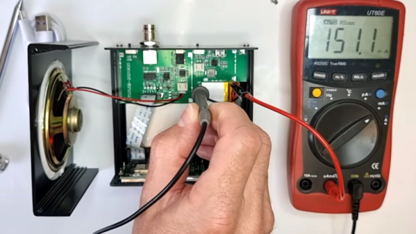
With the push to having most of a radio receiver as part of a PC, it might seem odd to have a standalone communication receiver, but [OM0ET] reviews the latest one he picked up, an ATS25. Inside isn’t much: a battery, a speaker, an encoder, and a Si4732 that provides the RF muscle.

It appears the receiver is pretty broadband which could be a problem. [OM0ET] suggests adding selectivity in the antenna or adding an extra board to use as a bandpass filter.

Continue reading “Shortwave Radio Picks Up Sideband”

Robust I2C And SPI In Space Thanks To Bus Isolation

Imagine you’re sending a piece of hardware to space on a satellite. Unless you’re buddy-buddy with NASA, it’s pretty unlikely you’ll ever be able to head up there and fix something if it goes wrong once it’s launched. Robust design is key, so that even in the event of a failure in one component, the rest of the hardware can keep working.

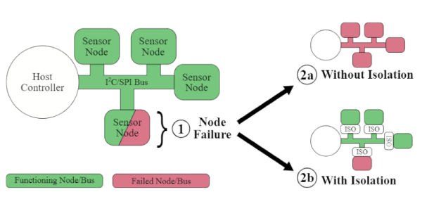
The example I2C isolation circuit from [Max’s] paper. The SPI implementation is even simpler.
[Max Holliday] found himself in this exact situation, running 69 I2C and SPI devices in a single satellite. Thus, he came up with circuits to auto-isolate devices from these buses in the event of an issue. That work is the subject of a research paper now available on the TechRxiv Preprint Server.

The problem is that these simple buses aren’t always the most robust, being vulnerable to single-point failures where one bad part takes down other parts of the bus. [Max] notes that vast numbers of sensors and devices rely on these standards, and it can be difficult or prohibitively expensive to design without them, so a solution was needed.

To fix this, [Max] developed a simple external circuit that could be placed on each node of a I2C or SPI communication bus. In the event of malfunction, that node can be cut off from the bus by this circuit, allowing the rest of the system to go on functioning.

With little more than a few transistors, MOSFETs and passives, you too could protect your buses from malfunctions using these techniques. [Max] did just that on the NASA V-R3x mission which flew successfully in January 2021 if you needed any further confirmation of the value of this technique.

It’s something that won’t bother the home hobbyist building a garage door opener, but it could be of great value to those designing systems that must fail gracefully if they fail at all. Be sure to share your best tips and tricks for robust SPI and I2C buses in the comments below!

Raspberry Pi Pico Makes For Expeditious Input Device

With its copious number of GPIO pins and native USB, the Raspberry Pi Pico is arguably the ideal microcontroller for developing your own platform agnostic USB Human Input Devices. But you don’t have to take our word for it. Check out how quickly the $4 USD board allowed [Alberto Nunez] to put together a pair of foot pedals for his computer.

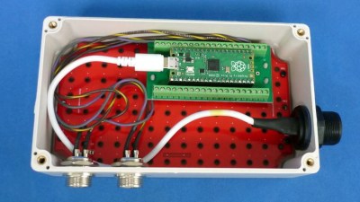
Wiring doesn’t get much easier than this.

A peek inside the enclosure reveals…well, not a whole lot. All that’s hiding inside that heavy-duty plastic box is the Pi Pico and some screw down terminals that let [Alberto] easily wire up the female bulkhead connectors for the pedals themselves. Incidentally, while you could certainly make your own pedals, the ones used for this project appear to be the sort of commercially available units we’ve seen used in similar projects.

With the hardware sorted, [Alberto] just needed to write the software. While he could have taken the easy way out and hard coded everything, we appreciate that his CircuitPython script loads its configuration from a text file. This allows you to easily configure which GPIO pins are hooked up to buttons, and what key codes to associate them with. He didn’t really need to go through this much effort for his own purposes, but it makes the project far easier to adapt for others, so our hats off to him.

If you’re looking for a bit more inspiration, our very own [Kristina Panos] put together a Python-powered macro foot stool that you can put under your desk for rapid fire keyboard shortcuts. Plus you can stand on it to reach the top shelf, if need be.

IC Shortage Keeps Linux Out Of Phone Charger, For Now

We’ve been eagerly following the development of the WiFiWart for some time now, as a quad-core Cortex-A7 USB phone charger with dual WiFi interfaces that runs OpenWrt sounds exactly like the sort of thing we need in our lives. Unfortunately, we’ve just heard from [Walker] that progress on the project has been slowed down indefinitely by crippling chip shortages.

At this point, we’ve all heard how the chip shortage is impacting the big players out there. It makes sense that automakers are feeling the pressure, since they are buying literally millions of components at a clip. But stories like this are a reminder that even an individual’s hobby project can be sidelined by parts that are suddenly 40 times as expensive as they were when you first put them in your bill of materials.

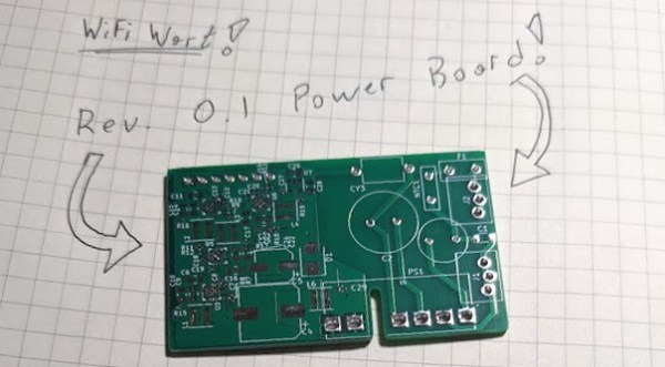
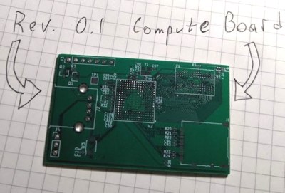
The new miniature compute board.

In this particular case, [Walker] explains that a power management chip you could get on DigiKey for $1.20 USD a few months ago is now in such short supply that the best offer he’s found so far is $49.70 a pop from an electronics broker in Shenzhen. It sounds like he’s going to bite the bullet and buy the four of them (ouch) that he needs to build a working prototype, but obviously it’s a no go for production.

Luckily, it’s not all bad news. [Walker] has made some good progress on the power supply board, which will eventually join the diminutive computer inside the USB charger enclosure. Part of the trick is that the device is still supposed to be a functional USB charger, so in addition to 5 VDC for the output port, the power supply also needs to produce 1.1 V, 1.35 V, 2.5 V, 3.0 V, and 3.3 V for the computer. We’re glad to see he’s taking the high road with his mains circuitry, making sure to use UL listed components and maintaining proper isolation.

When we last checked in on the WiFiWart back in July, [Walker] had already managed to boot Linux on his over-sized prototype board. Now he’s got PCBs in hand that look far closer to the final size and shape necessary to tuck them into a phone charger. It’s a shame that the parts shortage is slowing down progress, but we’re confident we’ll at least get to see a one-off version of the WiFiWart powered up before the year is out.