Irrighino, An Arduino Yun Based Watering System

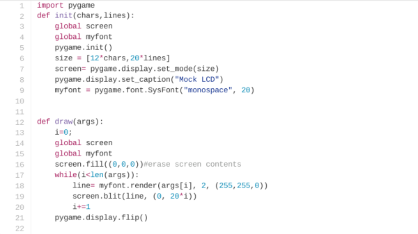
There are many different ways to keep your plants watered on a schedule. [Luca Dentella] just created a new one by building the irrighino watering system. He used standard off the shelf, hardware to keep it simple. Irrighino is a complete watering system based on the Arduino Yun, featuring a user friendly AJAX interface. This allows scheduling in a manner similar to creating appointments in Outlook. It’s also possible to manually control the various water solenoids. The code is fully customizable and open source, with code available from [Luca’s] github repository. The web interface is divided in to three tabs – “runtime” for manual control, “setup” to configure the scheduling, and “events” to view system logs.

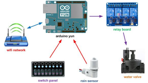
The Arduino Yun activates solenoid valves via a relay shield. A switch panel has indicator Status LED’s and three position switches. These allow the outputs to be switched off or on manually, or controlled via the Yun when in auto mode. [Luca] describes how to read three states of the switch (On-Off-On) when connected to a single analog input of the Arduino. He’s also got another tutorial describing how to connect a USB WiFi adapter to the Yun. This is handy since the Yun is mounted inside an enclosure where the signal strength is very weak. While the Yun has on-board WiFi, there is no possibility to attach an external antenna directly to the test SMA socket.

One interesting part is the commercial rain sensor. It’s a switch surrounded by a spongy material. When this material absorbs rain water, it begins to expand and triggers the switch. The Arduino sees the sensor as a simple digital input.

Check a short demo of his system in the video after the break.

Continue reading “Irrighino, An Arduino Yun Based Watering System”

Hackaday Prize Worldwide : New Delhi Kicad + Show And Tell

While Mumbai and Bengaluru have an active and large hacker community, New Delhi, India’s capital, seems to have leapfrogged ahead when it comes to hackerspaces – four at last count. So when the latest one in town, Maker’s Asylum, opened it’s doors last month, we decided to put together a hacker congregation to bring the community together and introduce them to the Hackaday Prize. Having already done Hackaday Prize bring-a-hack events in Mumbai and Bengaluru, we thought of doing something more substantial – a day long KiCad EDA workshop followed in the evening by a Show-n-Tell brag show.

Hackaday’s [Matt Berggren a.k.a. @technolomaniac] has done a couple of “Design a PCB from zero to WiFi with Hackaday!” Eagle EDA workshops recently. He designed a simple breakout board that allowed connecting an ESP-01 module to the USB port via an USB-UART cable with level conversion, pull up resistors and push button switches to make it easy to program. We had a slightly delayed start, so I quickly rushed through the awesome presentation that [Matt] has prepared, running through the “What is a PCB?” section and skipping the rest. We also discussed a couple of candidate designs for the day’s workshop – a pair of ATtiny line following robots, a simple Attiny SmartLED controller, but eventually, everyone got excited when I mentioned “ESP-8266” !

Continue reading “Hackaday Prize Worldwide : New Delhi Kicad + Show And Tell”

Find And Repair A 230kV 800Amp Oil-Filled Power Cable Feels Like Mission Impossible

How do you fix a shorted cable ? Not just any cable. An underground, 3-phase, 230kV, 800 amp per phase, 10 mile long one, carrying power from a power station to a distribution centre. It costs $13,000 per hour in downtime, counting 1989 money, and takes 8 months to fix. That’s almost $75 million. The Los Angeles Department of Water and Power did this fix about 26 years ago on the cable going from the Scattergood Steam Plant in El Segundo to a distribution center near Bundy and S.M. Blvd. [Jamie Zawinski] posted details on his blog in 2002. [Jamie] a.k.a [jwz] may be familiar to many as one of the founders of Netscape and Mozilla.

To begin with, you need Liquid Nitrogen. Lots of it. As in truckloads. The cable is 16 inch diameter co-axial, filled with 100,000 gallons of oil dielectric pressurised to 200 psi. You can’t drain out all the oil for lots of very good reasons – time and cost being on top of the list. That’s where the LN2 comes in. They dig holes on both sides (20-30 feet each way) of the fault, wrap the pipe with giant blankets filled with all kind of tubes and wires, feed LN2 through the tubes, and *freeze* the oil. With the frozen oil acting as a plug, the faulty section is cut open, drained, the bad stuff removed, replaced, welded back together, topped off, and the plugs are thawed. To make sure the frozen plugs don’t blow out, the oil pressure is reduced to 80 psi during the repair process. They can’t lower it any further, again due to several compelling reasons. The cable was laid in 1972 and was designed to have a MTBF of 60 years.

Continue reading “Find And Repair A 230kV 800Amp Oil-Filled Power Cable Feels Like Mission Impossible”

Android-based Reflow Brings Solder Profiles To Your Lab

[Andy Brown] is a prolific hacker and ends up building a lot of hardware. About a year back, he built a reflow oven controller. The board he designed used a large number of surface mount parts. This made it seem like a chicken or egg first problem. So he designed a new, easy to build, Android based reflow controller. The new version uses just one, easy to solder surface mount part. By putting in a cheap bluetooth module on the controller, he was able to write an app which could control the oven using any bluetooth enabled Android phone or tablet.

The single PCB is divided into the high voltage, mains powered section separated from the low power control electronics with cutout slots to take care of creepage issues. A BTA312-600B triac is used to switch the oven (load) on and off. The triac is controlled by a MOC3020M optically isolated triac driver, which in turn is driven by a micro controller via a transistor. The beefy 12Amp T0220 package triac is expected to get hot when switching the 1300W load, and [Andy] works through the math to show how he arrived at the heat sink selection. To ensure safety, he uses an isolated, fully encased step down transformer to provide power to the low voltage, control section. One of his requirements was to detect the zero cross over of the mains waveform. Using this signal allows him to turn on the triac for specific angle which can be varied by the micro controller depending on how much current the load requires. The rectified, but unfiltered ac signal is fed to the base of a transistor, which switches every time its base-emitter voltage threshold is reached.

For temperature measurement, [Andy] was using a type-k thermocouple and a Maxim MAX31855 thermocouple to digital converter. This part caused him quite some grief due to a bad production batch, and he found that out via the eevblog forum – eventually sorted out by ordering a replacement. Bluetooth functions are handled by the popular, and cheap, HC-06 module, which allows easy, automatic pairing. He prototyped the code on an ATmega328P, and then transferred it to an ATmega8 after optimising and whittling it down to under 7.5kb using the gcc optimiser. In order to make the board stand-alone, he also added a header for a cheap, Nokia 5110 display and a rotary encoder selector with switch. This allows local control without requiring an Android device.

Gerbers (zip file) for the board are available from his blog, and the ATmega code and Android app from his Github repo. The BoM list on his blog makes it easy to order out all the parts. In the hour long video after the break, [Andy] walks you through solder tip selection, tips for soldering SMD parts, the whole assembly process for the board and a demo. He then wraps it up by connecting the board to his oven, and showing it in action. He still needs to polish his PID tuning and algorithm, so add in your tips in the comments below.

Continue reading “Android-based Reflow Brings Solder Profiles To Your Lab”

Homemade Camera Stabilizer

We’ve featured quite a few camera gimbals and steady cams here, but this one stands out. For one, [Daniel Rhyoo] was in his sophomore year when he built it. His 2-axis camera gimbal uses brushless DC motors, and is made out of carbon fiber.

[Daniel] machined the carbon fiber parts on a CNC desktop mill and some hand tools. And he also had to teach himself Solid Works to design it. In his slick DIY guide, he starts off by listing the parts and where to source them from, along with the tools needed. Most gimbals use servos for axis movements, which limits the range and do not provide very smooth motion. Brushless motors overcome these limitations allowing a nice, smooth moving gimbal to be built with a wide range of movement. When [Aleksey Moskalenko] introduced the AlexMos brushless motor controller, [Daniel] ordered it out, and then waited until he could get his hands on the right kind of motors. CAD files for all of the machined parts are available for download (.zip file).

He then goes on to blog his build progress, with ample photos to describe the machining and assembly. He does a couple of nice design choices along the way – like using press-nuts to make assembly and dis-assembly easy, and dismantling one of the motors and replacing its shaft with a custom, longer one instead of using a coupler to extend it. At the end, the result is not only a nice looking, light weight rig, but one that works very well thanks to the motors and controller that he used. Check out the video below to see it in action.

Continue reading “Homemade Camera Stabilizer”

CCCamp 2015 Rad1o Badge

Conference badges are getting more complex each year. DEFCON, LayerONE, Shmoocon, The Next Hope, Open Hardware Summit, The EMF, SAINTCON, SXSW Create, The Last Hope, TROOPERS11, ZaCon V and of course the CCC, have all featured amazing badges over the years. This years CCCamp 2015 rad1o badge is taking things several notches higher. The event will run from 13th through 17th August, 2015.

The rad1o Badge contains a full-featured SDR (software defined radio) transceiver, operating in a frequency range of about 50 MHz – 4000 MHz, and is software compatible to the HackRF One open source SDR platform. The badge uses a Wimax transceiver which sends I/Q (in-phase/quardrature-phase) samples in the range of 2.3 to 2.7 GHz to an ARM Cortex M4 CPU. The CPU can process the data standalone for various applications such as FM radio, spectrogram display, RF controlled power outlets, etc., or pass the samples to a computer using USB 2.0 where further signal processing can take part, e.g. using GnuRadio. The frequency range can be extended by inserting a mixer in the RF path. Its got an on-board antenna tuned for 2.5GHz, or an SMA connector can be soldered to attach an external antenna. There’s a Nokia 6100 130×130 pixel LCD and a joystick, which also featured in the earlier CCCamp 2011 badge known as the r0ket.

A 3.5mm TRRS audio connector allows hooking up a headphone and speaker easily. The LiPo battery can be charged via one of the USB ports, while the other USB port can be used for software updates and data I/O to SDR Software like GnuRadio. Check out the project details from their Github repository and more from the detailed wiki which has information on software and hardware. There’s also a Twitter account if you’d like to follow the projects progress.

This years Open Hardware Summit also promises an awesome hackable badge. We’ll probably feature it before the OHS2015 conference in September.

Thanks to [Andz] for tipping us off about this awesome Badge.

Virtual LCD Using Python

[Prashant Mohta] got hold of a Raspberry Pi, a 16×2 LCD display and got down to writing a simple game in Python. Pretty soon, he realized that it was cumbersome to have the Ras-Pi and LCD connected when all he wanted to do was write the code. So he wrote a simple Python module which renders the LCD on his computer display. A simple, quick, useful hack.

[Prashant]’s code relies on the use of Pygame, a set of Python modules designed for writing games. His code uses just two functions – one to define the LCD (characters and number of lines) while the other draws the characters on the screen by looking up an array. The code is just under 20 lines and available from his Github repo. It will be useful to those who are getting started on Python to help them understand some basics. Python is awesome and writing Python code is pretty simple.

This might draw some flak from the naysayers so if you’re commenting below on the merits, or not, of Python, just keep your comments civil and healthy. In the video below, unrelated to this hack, [Raymond Hettinger] talks about “What makes Python so Awesome”!

Continue reading “Virtual LCD Using Python”