A Bullet Time Video Booth You Can Build

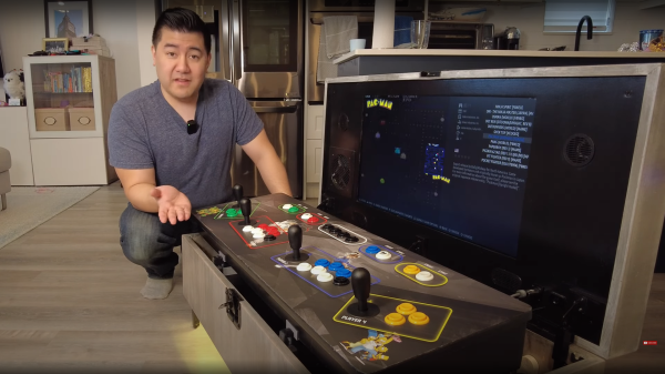
[Sebastian Staacks] built a video booth for his wedding, and the setup was so popular with family, that it was only fitting to do one better and make some improvements to the setup, Matrix-style. The “bullet time” video effect was introduced by the classic movie franchise and makes for a splendid video transition effect for video montages.

Hardware-wise, the effect is pretty expensive, requiring many cameras at various angles to be simultaneously triggered, in order to capture the subject in a fixed pose with a rotating camera. Essentially you need as many cameras as frames in the sequence, so even at 24 frames per second (FPS), that’s a lot of hardware. [Sebastian] cheated a bit, and used a single front-facing camera for the bulk of the video recording, and twelve individual DSLRs covering approximately 90 degrees of rotation for the transition. More than that is likely impractical (not to mention rather expensive) for an automated setup used in as chaotic an environment as a wedding reception! So, the video effect is quite the same as in the movies, as this is a fixed pose, but it still looks pretty good.

A Pico-W hidden in there providing a BT connected interface button

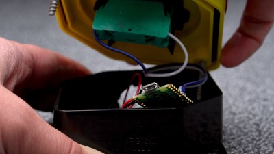
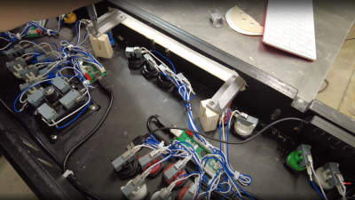
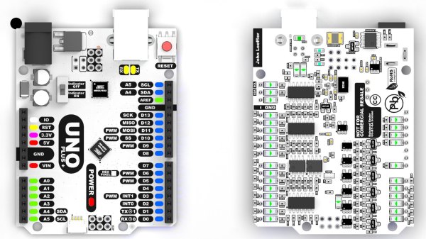
[Sebastian] did consider going down the Raspberry Pi plus Pi-cam route, but once you add in a lens and the hassle of the casing and mounting hardware, not to mention availability and cost, snagging a pile of old DLSRs looks quite attractive. Connectivity to the camera is a simple 3.5 mm jack for the focus and trigger inputs, with frames read out via a USB connection.

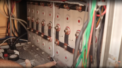
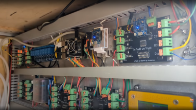
For practical deployment, the camera batteries were replaced with battery eliminator adapters which step-up the 5 V from the USB connection to the 7.4 V the cameras need, but the current spike produced by the coordinated trigger of all twelve cameras overwhelmed any power supply available. The solution, to be practical, and not at all elegant, is to just have lots of power supplies hidden in a box. Sometimes you’ve just got a job to do.

Reproducing this at home might be a bit awkward unless you have exactly the same hardware to hand, but the principles are sound, and there are a few interesting details to dig into, if you were so inclined.

We’ve seen a few takes on the bullet-time effect over the years. We featured a Raspberry Pi-based hack, a couple of years back, and earlier still, someone even built a rig to take bullet-time videos of Tesla coil discharges, because why not?

Continue reading “A Bullet Time Video Booth You Can Build”

Op-Amp Challenge: Interactive Analog LED Wave Array

A while back, [Chris Lu] was studying how analog circuits, specifically op-amps can be used to perform mathematical operations and wondered if they could be persuaded to solve differential equations, such as the wave equation. After sitting on the idea for a few years, it was time to make it a reality, and the result is an entry into the Op-Amp Challenge.

Unlike many similar interactive LED matrix displays that are digital in nature (because it’s a lot easier), this design is pure analog, using many, many op-amps. A custom PCB houses a 4×4 array of compute units, each with a blue and white LED indicating the sign and magnitude of the local signal.

The local input signal is provided by an IR photodiode, AC coupled to only respond to change, with every other circuit sharing a sensor to keep it simple. Each circuit is connected to its immediate neighbors on the PCB, and off the PCB via board-to-board connectors. This simple scheme makes this easily scalable if desired in the future.

[Chris] does a great job of breaking down the math involved, which makes this project a neat illustration of how op-amp circuits can implement complex mathematical problems in an easy-to-understand process. Even more op-amps are pressed into service for generating the split-rail voltage reference and for amplifying the weak photodiode signals, but the computation circuit is the star of the show.

We like analog computing a fair bit around these parts. Here’s a little something we were previously drooling over.

Continue reading “Op-Amp Challenge: Interactive Analog LED Wave Array”

A 4-Player Arcade Hidden Inside A Coffee Table

[Ed] from 50% Awesome on YouTube wanted to build a retro gaming system with a decent screen size, but doesn’t have a great deal of space to site it in, so a good compromise was to make a piece of useful furniture and hide all the fun parts inside.

Building an arcade machine usually involves a lot of wiring

This video two-part build log shows a lot of woodwork, with a lot of mistakes (happy accidents, that are totally fine) made along the way, so you do need to repeat them. Essentially it’s a simple maple-veneered plywood box, with a thick lid section hosting the display and some repositioned speakers. This display is taken from a standard LG TV with the control PCB ripped out. The power button/IR PCB was prised out of the bezel, to be relocated, as were the two downwards-facing speakers. The whole collection of parts was attached to a front panel, with copious hot glue, we just hope the heavy TV panel was firmly held in there by other means!

Continue reading “A 4-Player Arcade Hidden Inside A Coffee Table”

Converting On-Grid Electronics To Off-Grid

Husband and wife team [Jason & Kara] hail from Canada, and in 2018, after building their own camper, sold up their remaining earthly goods and headed south. If you’re not aware of them, they documented their journey on their YouTube channel, showing many interesting skills and hacks along the way. The video we’re highlighting today shows a myriad of ways to power all the DC-consuming gadgets this they lug along with them.

LiFePO4 batteries are far superior to lead acid for mobile solar installations.

Their heavily modded F-550 truck houses 12kWh of LiFePO4 batteries and a 1.5kW retractable solar array, with a hefty inverter generating the needed AC power. They weren’t too happy with the conversion losses from piles of wall warts that all drained a little power, knowing that the inverter that fed them was also not 100% efficient. For example, a typical laptop power brick gets really hot in a short time, and that heat is waste. They decided to run as much as possible direct from the battery bank, through different DC-DC converter modules in an attempt to streamline the losses a little. Obviously, these are also not 100%

Home, sorry, truck automation system

efficient, but keeping the load off the inverter (and thus reducing dependency upon it, in the event of another failure) should help stem the losses a little. After all as [Jason] says, Watts saved are Watts earned, and all the little lossy loads add up to a considerable parasitic drain.

One illustration of this is their Starlink satellite internet system consumes about 60W when running from the inverter, but only 28W when running direct from DC. Over the course of 24 hours, that’s not far off 1kWh of savings, and if the sun isn’t shining, then that 12kWh battery isn’t going to stretch as far.

There are far too many hacks, tips, and illustrations of neat space and power-saving solutions everywhere, to write here. Those interested in self-build campers or hacking a commercial unit may pick up a trick or two.

Continue reading “Converting On-Grid Electronics To Off-Grid”

Hackaday Prize 2023: Uno Plus+ Updates A Classic

As an introduction to embedded electronics and programming in a straightforward environment, there isn’t much out there that can hold a torch to the Arduino Uno. Cheap (especially if you count the clones), easy to find, and quick to deploy, with countless support libraries, it’s a go-to for many a hack. This scribe simply can’t remember how many he’s bought, hacked, and deployed over the years. But can it be improved? [John Loeffler] thinks so, and his 2023 Hackaday Prize entry, the Uno Plus+ could be the one.

If this is too much bling for you, there is a version with LEDs adjacent to non-illuminated headers.

After clearing the top deck of extraneous components (by shoving them on the bottom) there was much more space to expand the header labeling, so there can be no accidental misplacement of those DuPont wires this thing will inevitably sprout randomly.

The board also has an additional Stemma/Qwiic connector and a Neopixel LED for indication duties. Also sitting on the PCB bottom are a ton of opamps, to drive the header indicators. Yes, this board has a full set of colour-coded LED bling indicators, showing the logical state of each and every pin on all headers, giving an easy way to check the desired activity is occurring. Plus it looks cool. Illuminated headers? YES!

Think the Uno too light on resources to perform any meaningful modern workloads? Think again!

A Crash Course On How MRI Machines Work

Of all the high-tech medical gadgets we read about often, the Magnetic Resonance Imaging (MRI) machine is possibly the most mysterious of all. The ability to peer inside a living body, in a minimally invasive manner whilst differentiating tissue types, in near real-time was the stuff of science fiction not too many years ago. Now it’s commonplace. But how does the machine actually work? Real Engineering on YouTube presents the Insane Engineering of MRI Machines to help us along this learning curve, at least in a little way.

Both types of gradient coil are stacked around the subject inside the main field coil

The basic principle of operation is to align the spin ‘axis’ of all the subject’s hydrogen nuclei using an enormous magnetic field produced by a liquid-helium-cooled superconducting electromagnet. The spins are then perturbed with a carefully tuned radio frequency pulse delivered via a large drive coil.

After a short time, the spins revert back to align with the magnetic field, remitting a radio pulse at the same frequency. Every single hydrogen nucleus (just a proton!) responds at roughly the same time, with the combined signal being detected by the receive coil (often the same physical coil as the driver.)

Time taken for the perturbed spin to return to magnetic alignment

There are two main issues to solve. Obviously, the whole body section is ‘transmitting’ this radio signal all in one big pulse, so how do you identify the different areas of 3D space (i.e. the different body structures) and how do you differentiate (referred to as contrast) different tissue types, such as determine if something is bone or fat?

By looking at the decay envelope of the return pulse, two separate measures with different periods can be determined; T1, the spin relaxation period, and T2, the total spin relaxation period. The first one is a measure of how long it takes the spin to realign, and the second measures the total period needed for all the individual interactions between different atoms in the subject to settle down. The values of T1 and T2 are programmed into the machine to adjust the pulse rate and observation time to favor the detection of one or the other effect, effectively selecting the type of tissue to be resolved.

Time taken for the relative phasing inside a tissue locality to settle down to the same average spin alignment

The second issue is more complex. Spatial resolution is achieved by first selecting a plane to virtually slice the body into a 2D image. Because the frequency of the RF pulse needed to knock the proton spin out of alignment is dependent upon the magnetic field strength, overlaying a second magnetic field via a gradient coil allows the local magnetic field to be tuned along the axis of the machine and with a corresponding tweak to the RF frequency an entire body slice can be selected.

All RF emissions from the subject emanate from just the selected slice reducing the 3D resolution problem to a 2D problem. Finally, a similar trick is applied orthogonally, with another set of gradient coils that adjust the relative phase of the spins of stripes of atoms through the slice. This enables the use of a 2D inverse Fourier transform of multiple phase and frequency combinations to image the slice from every angle, and a 2D image of the subject can then be reconstructed and sent to the display computer for the operator to observe.

See? It’s easy.

We cover MRI technology from time to time, here’s a little update on state-of-the-art resolution for those wishing the dig a little deeper.

Continue reading “A Crash Course On How MRI Machines Work”

Op Amp Contest: Magnetic Core Memory The Dr Cockroach Way

No matter how memory technology marches on, magnetic core memory is still cool. Radiation-hard, nonvolatile, and so pretty. What’s there not to love? [Mark Nesselhaus] is no stranger to fun in-your-face electronics builds — judging from his hackaday.io projects — and this entry to the Hackaday Op-Amp contest is no outlier. This is a sixteen-bit magnetic core RAM demonstrator built upon glass using copper tape and solder, which always looks great and is actually not all that hard to do yourself provided you grab a new scalpel blade from the pack before starting.

Transformer-coupled differential front-end amplifier driving an SR latch.

For the uninitiated, the crossed X and Y wires each host a hard magnetic toroid which can only be magnetised by a field beyond a certain threshold due to the shape of the B-H curve of ferrite materials. The idea is for a required threshold current, drive the selected X line and Y line each with a current half of this value, so that only the selected core bit ‘sees’ the full field value, and flips state. This means that only a single bit can be written for each core plane, so to form longer words these layers are stacked, producing some wonderful cubic structures. These magnetic circuits are responsible for putting a human on the moon.

Reading the bit state is basically the opposite. A third sense wire is passed sequentially through each bit in the array. By driving a current the opposite way through the selected core bit, if the core was previously magnetised then the sense wire will read a short pulse that can be amplified and registered. The eagle-eyed will realise that reading is a destructive process, so this needs to be followed up by a write-back process to refresh the bit, although the core state will persist without power, giving the memory nonvolatile behaviour.

[Mark] utilises a simple discrete transistor differential transformed-coupled front end which senses the tiny current pulse and passes it along to a Set-Reset latch for visualisation. This simple concept could easily be extended to make this a practical memory, but for now, addressing is courtesy of a pair of crocodile clips and a discrete write/read pulse switch. We will watch with interest how far this goes.

DIY core memory builds are not a regular occurrence around these parts, but we see them from time to time, like this polished 64-bit setup. Core arrays are not the only magnetic memory in town, we’ve also seen DIY core rope memories as well.

Continue reading “Op Amp Contest: Magnetic Core Memory The Dr Cockroach Way”