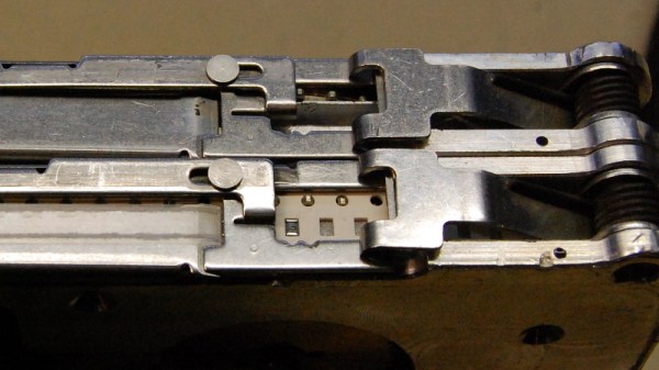
Many of Hackaday’s readers will be no stranger to surface mount electronic components, to the extent that you’ll likely be quite comfortable building your own surface-mount projects. If you have ever built a very large surface-mount project, or had to do a number of the same board though, you’ll have wished that you had access to a pick-and-place machine. These essential components of an electronics assembly line are CNC robots that pick up components from the reels of tape in which they are supplied, and place them in the appropriate orientation in their allotted places on the PCB. They are an object of desire in the hardware hacker community and over the years we’ve seen quite a few home-made examples. Their workings are easy enough to understand, but there is still much to gain by studying them, thus it was very interesting indeed to see a friend acquiring a quantity of surplus Siemens component feeders from an older industrial pick-and-place machine. A perfect opportunity for a teardown then, to see what makes them tick.
Author: Jenny List3457 Articles
Auto Tuning For A Vintage Stereo
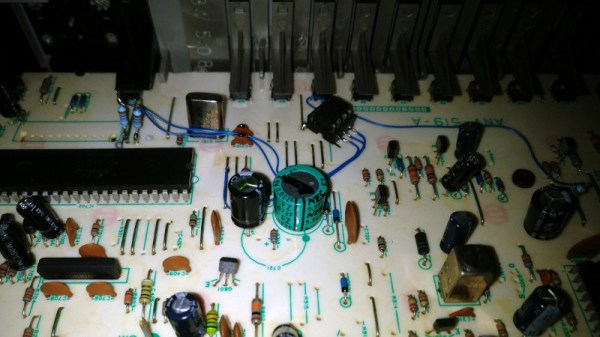
In 1984 there weren’t many ways to listen to high-quality music, so an FM tuner was an essential part of any home hi-fi system. The Pioneer TX-950 picked up by [The Curious Lorenz] would have been someone’s pride and joy, with its then-cutting-edge microprocessor control, digital PLL tuning, and seven-segment displays. Astoundingly it doesn’t have an auto-tuning function though, so some work to implement the feature using an ATtiny85 was called for.
A modern FM tuner would be quite likely to use an all-in-one tuner chip using SDR technology under the hood, but this device from another era appears to be a very conventional analog tuner to which the PLL and microprocessor have been grafted. There are simple “Up” and “Down” buttons and a “Station tuned” light. One might imagine that given these the original processor could have done autotune. At least the original designers were kind enough to provide the ATtiny with the interfaces it needs. Pressing either button causes it to keep strobing its line until the “Station tuned” line goes high, at which point it stops. It’s an extremely simple yet effective upgrade, and since the ATtiny is so small it’s easily placed on top of the original PCB. The result is an ultra-modern tuner from 1984, that’s just that little bit more modern than it used to be.
If you don’t have a vintage FM radio, you can always build its modern equivalent.
A 3D – To – 2D Converter To Make Plots From STLs.
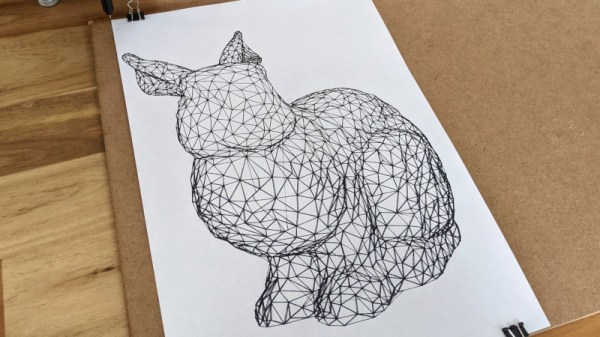
We’ve become used to finding models on websites such as Thingiverse and downloading them to print. After all, whose hackerspace doesn’t have a pile of novelty prints? How about printing them on paper? For the plotter enthusiast that can be particularly annoying. Never fear, [Trammell Hudson] is here with an online 3D to 2D converter just for plotters. [Trammell’s] creation makes a vector image suitable for a plotter while eliminating spurious behind-the-scenes lines.
Plotter drawings are the pen-and-paper equivalent of a vector CRT display, in which the graphics are printed as continuous strokes. Rendering a 3D model as a wireframe for a plotter requires the removal of any pen strokes that comes from the 3D space behind the surface in view. Loading various models into the web page seemed to do a pretty good job of this, though the ubiquitous Benchy 3d printer test model lived up to its billing as a torture test in taking several minutes to render.
As anyone who has followed the #PlotterTwitter social media hashtag will know, there is a considerable community of pen plotter enthusiasts who are pushing the boundaries of what their machines can do. [Trammell] has posted his plotter producing some of the work created with this tool, and we can see that it’s likely to work better with lower-poly models.
We’ve featured a lot of plotters over the years as they seem to be a popular project. If you’d like one then they can be made from the most available parts, including those scavenged from scrap DVD drives, or printers.
Still Got Film To Scan? This Lego And Raspberry Pi Scanner Is For You
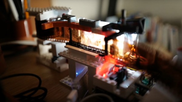
There was a time during the early years of mass digital photography, when a film scanner was a common sight. A small box usually connected to a USB port, it had a slot for slides or negatives. In 2020 they’re a rare breed, but never fear! [Bezineb5] has a solution in the shape of an automated scanner using a Radpberry Pi and a mechanism made of Lego.
The Lego mechanism is a sprocket feeder that moves the film past the field of view from an SLR camera. The software on the Pi runs in a Docker container, and features a machine learning approach to spotting frame boundaries. This is beyond the capabilities of the Pi, so is offloaded to a Google Coral accelerator.
The whole process is automated with the Pi controlling not only the Lego but also the camera, to the extent of retrieving the photos from it to the Pi. There’s a smart web interface to control everything, making the process — if you’ll excuse the pun — a snap. There’s a video of it in action, that you can see below the break.
We’ve featured many film scanner projects over the years, one that remains memorable is this 3D printed lens mount.
Continue reading “Still Got Film To Scan? This Lego And Raspberry Pi Scanner Is For You”
A Xilinx Zynq Linux FPGA Board For Under $20? The Windfall Of Decommissioned Crypto Mining
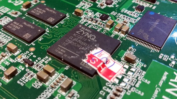
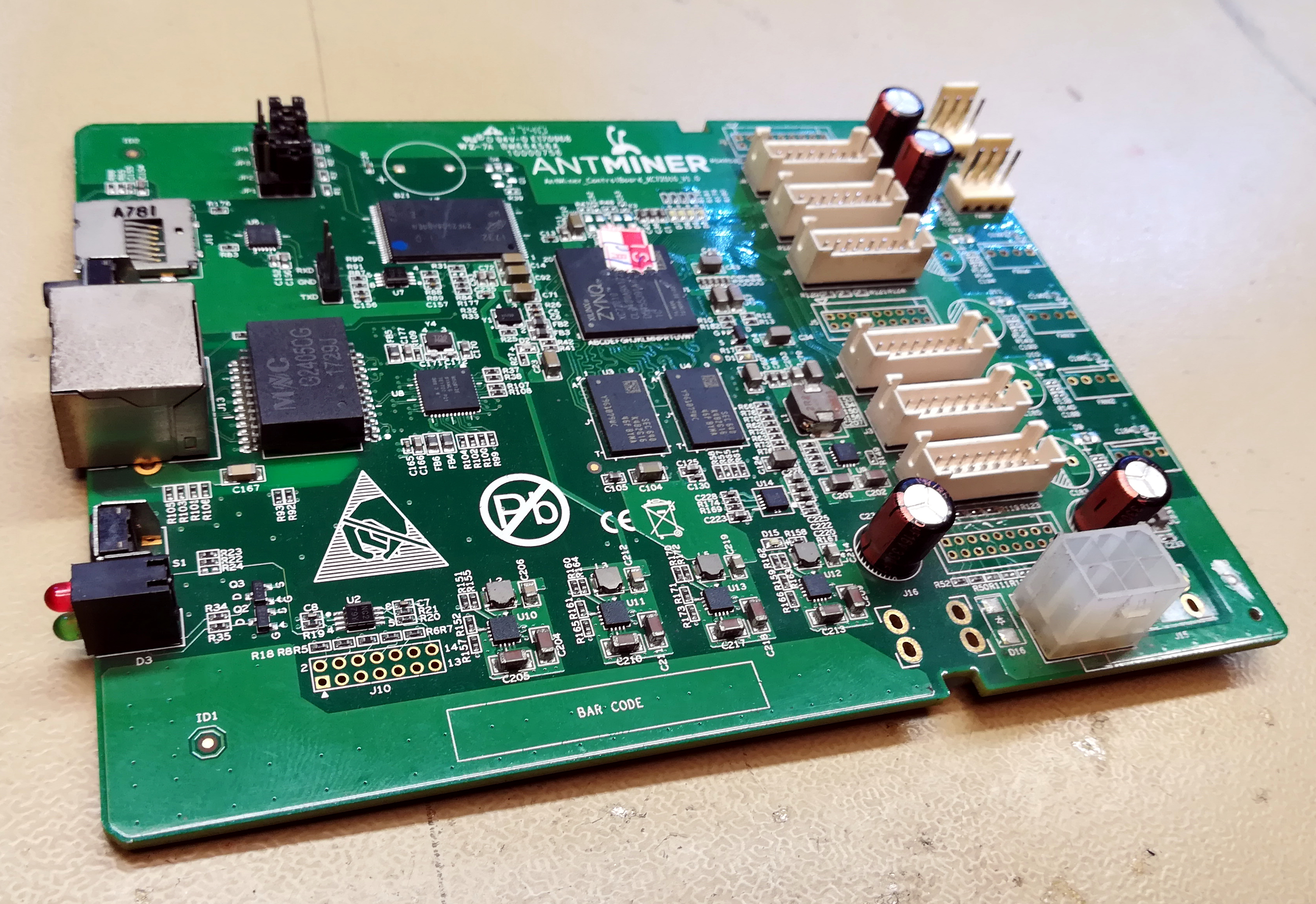
One of the exciting trends in hardware availability is the inexorable move of FPGA boards and modules towards affordability. What was once an eye-watering price is now merely an expensive one, and no doubt in years to come will become a commodity. There’s still an affordability gap at the bottom of the market though, so spotting sub-$20 Xilinx Zynq boards on AliExpress that combine a Linux-capable ARM core and an FPGA on the same silicon is definitely something of great interest. A hackerspace community friend of mine ordered one, and yesterday it arrived in the usual anonymous package from China.
There’s a Catch, But It’s Only A Small One

There are two boards to be found for sale, one featuring the Zynq 7000 and the other the 7010, which the Xilinx product selector tells us both have the same ARM Cortex A9 cores and Artix-7 FPGA tech on board. The 7000 includes a single core with 23k logic cells, and there’s a dual-core with 28k on the 7010. It was the latter that my friend had ordered.
So there’s the good news, but there has to be a catch, right? True, but it’s not an insurmountable one. These aren’t new products, instead they’re the controller boards for an older generation of AntMiner cryptocurrency mining rigs. The components have 2017 date codes, so they’ve spent the last three years hooked up to a brace of ASIC or GPU boards in a mining data centre somewhere. The ever-changing pace of cryptocurrency tech means that they’re now redundant, and we’re the lucky beneficiaries via the surplus market.
Who Says Solder Paste Stencils Have To Be CNC Cut?
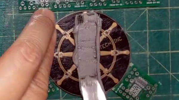
Imagine having a surface mount kit that you’d like to stencil with solder paste and reflow solder, but which doesn’t come with a solder stencil. That was what faced [Honghong Lu], and she rose to the challenge by taking a piece of PET sheet cut from discarded packaging and hand-cutting her own stencil. It’s not a huge kit, the Technologia Incognita 2020 kit, but her home-made stencil still does an effective job.
So how does one create a solder stencil from household waste? In the video we’ve put below the break, she starts with her packaging, and cuts from it a square of PET sheet. It’s 0.24mm thick, which is ideal for the purpose. She then lays it over the PCB and marks all the pads with a marker pen, before cutting or drilling the holes for the pads. The underside is then sanded to remove protruding swarf, and the stencil can then be used in the normal way. She proves it by stenciling the solder paste, hand placing the parts, and reflowing the solder on a hotplate.
It’s clear that this is best suited to smaller numbers of larger components, and we’ll never use it to replace a laser-cut stencil for a thousand tiny 0201 discretes. But that’s not the point here, it’s an interesting technique for those less complex boards, and it’s something that can be tried by anyone who is curious to give stenciling and reflowing a go and who doesn’t have a project with a ready-cut stencil. And for that we like it.
Making your own stencils doesn’t have to include this rather basic method. They can be etched, or even 3D printed.
Continue reading “Who Says Solder Paste Stencils Have To Be CNC Cut?”
A Portable Serial Terminal That Should Be From The 1970s
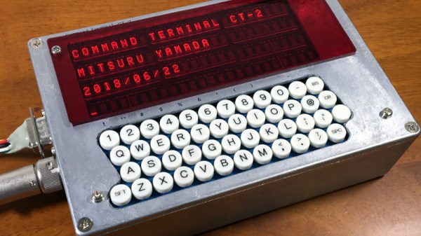
The humble standalone serial terminal might be long gone from the collective computing experience, but in the ghostly form of a software virtual terminal and a serial converter it remains the most basic fall-back and essential tool of the computer hardware hacker. [Mitsuru Yamada] has created the product that should have been made in the serial terminal’s heyday, a standalone handheld terminal using a 6809 microprocessor and vintage HP dot matrix LEDs. In a die-cast box with full push-button keyboard it’s entirely ready to roll up to a DB-25 wall socket and log into the PDP/11 in the basement.
Using today’s parts we might achieve the same feat with a single-chip microcontroller and a small LCD or OLED panel, but with an older microcomputer there is more system-building required. The 6809 is a wise choice from the 1970s arsenal because it has some on-board RAM, thus there’s no need for a RAM chip. Thus the whole thing is achieved with only a 2716 EPROM for the software, a 6850 UART with MAX232 driver for the serial port, and a few 74 chips for glue logic, chip selects, and I/O ports to handle keyboard and display. There’s no battery in the case, but no doubt that could be easily accommodated. Also there’s not much information on the keyboard itself, but in the video below we catch a glimpse of its wiring as the box is opened.
The value in a terminal using vintage parts lies not only in because you can, but also in something that can’t easily be had with a modern microcontroller. These parts come from a time when a computer system had to be assembled as a series of peripherals round the microprocessor because it had few onboard, leading to a far more in-depth understanding of a computer system. It’s not that a 6809 is a sensible choice in 2020, more that it’s an interesting one.
By comparison, here’s a terminal using technology from today.
Continue reading “A Portable Serial Terminal That Should Be From The 1970s”