An Electromagnet Brings Harmony To This Waving Cat

We’ve noticed waving cats in restaurants and stores for years, but even the happy bobbing of their arm didn’t really catch our attention. Maybe [Josh] had seen a couple more than we have when it occurred to him to take one apart to see how they work. They are designed to run indoors from unreliable light sources and seem to bob along forever. How do the ubiquitous maneki-neko get endless mechanical motion from one tiny solar cell?
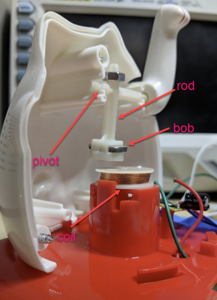
Perhaps unsurprisingly given the prevalence and cost of these devices, the answer is quite simple. The key interaction is between a permanent magnet mounted to the end of the waving arm/pendulum and a many-turn wire coil attached to the body. As the magnet swings over the coil, its movement induces a voltage. A small blob of analog circuitry reacts by running current through the coil. The end effect is that it “senses” the magnet passing by and gives it a little push to keep things moving. As long as there is light the circuit can keep pushing and the pendulum swings forever. If it happens to stop a jolt from the coil starts the pendulum swinging and the rest of the circuit takes over again. [Josh] points to a similar circuit with a very nice write up in an issue of Nuts and Volts for more detail.

We’ve covered [Josh]’s toy teardowns before and always find this category of device particularly interesting. Toys and gadgets like the maneki-neko are often governed by razor-thin profit margins and as such must satisfy an extremely challenging intersection of product constraints, combining simple design and fabrication with just enough reliability to not be a complete disappointment.

For more, watch [Josh] describe his method in person after the break, or try flashing his code to an Arduino and make a waving cat of your own.

Continue reading “An Electromagnet Brings Harmony To This Waving Cat”

Retro Rebuild Recreates SGI Workstation Demos On The Go

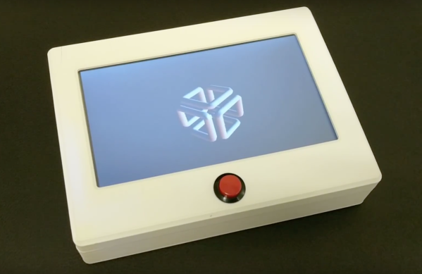
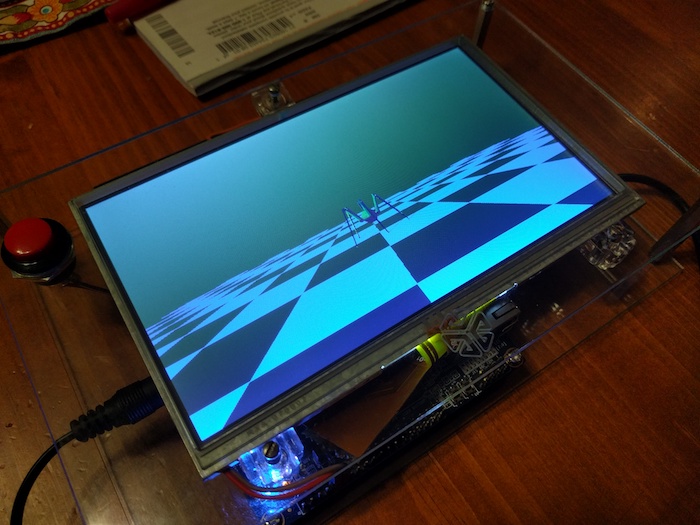
When [Lawrence] showed us the Alice4 after Maker Faire Bay Area last weekend it wasn’t apparent how special the system was. The case is clean and white, adorned only with a big red button below a 7″ screen with a power switch around the back. When the switch is flicked the system boots to display a familiar animation and drops you at a menu. Poking around from here elicits a variety of self-contained graphics demos, some interactive. So this is a Raspberry Pi in a box playing videos, right? Not even close.

Often retro computing focuses on personal computer systems. When they were new the 8-bit graphics or intricate 2D sprites were state of the art, but now their appeal tends towards learning opportunities and the thrill of nostalgia. This may still be true of Alice4, the system [Brad, Lawrence, Mike, and Chris] put together to run Silicon Graphics (SGI) demos from the mid 1980’s but it’s not the whole story. [Lawrence] and [Brad] had both worked at SGI during its heyday and had fond memories of the graphics demos that shipped with those mammoth workstation. So they built Alice4 from the FPGA up to run those very same demos in real-time.

Thanks to Moore’s law, today’s embedded systems put yesterday’s powerhouses within reach. [Lawrence] and [Brad] found the old demo code in a ratty FTP server, and tailor-made Alice4’s software and hardware to run them natively. [Brad] wrote a libgl which implements the subset of the IrisGL API needed to support their selected set of demos. The libgl emits sets of triangles to the SDRAM where [Lawrence’s] HDL running on the onboard FPGA fetches them to interpolate color and depth and draw the result on-screen. Together they allow the $99 Altera Cyclone V development board at Alice4’s heart to run these state of the art demos in the palm of your hand.

Alice4 is open source and extensively documented. Peruse the archeology of reverse engineering the graphics API or the discussion of FIFO design in the FPGA. If those don’t sate your appetite check out a video of Alice4 in action after the break.

Continue reading “Retro Rebuild Recreates SGI Workstation Demos On The Go”

Open Source Calculator Teaches Us About Quality Documentation

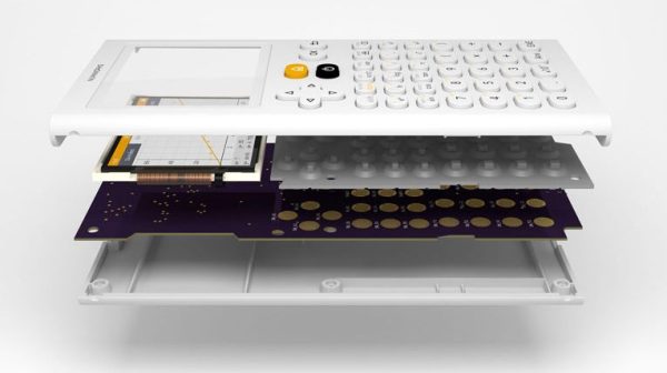
Graphing calculators are one of those funny markets that never seem to change. Standardized testing has created a primordial stew of regulatory capture in which ancient technology thrives at modern retail prices while changing little. The NumWorks calculator certainly isn’t the first competitor to challenge the Texas Instruments dynasty with a more modern interface (and a design from this decade), but behind it’s subtle color pops and elegant lines lies the real gem; a fantastically well documented piece of open source hardware. The last time we wrote about the NumWorks, it was to demonstrate a pretty wild hack that embedded an entire Pi Zero but it’s worth drawing attention to the calculator itself.

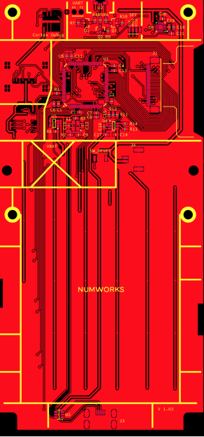
Hackaday readers traveling to the NumWorks website might spy the section at the bottom of the page titled “Developers” with tantalizing links like “Hardware,” “Software,” and “GitHub.” These lead to a wealth of knowledge about how the product is put together and sources to build the enclosure and firmware yourself (the PCB schematic and layout sources seem to be missing, though there is this handy gerber viewer). However merely posting sources is a low bar NumWorks far exceeds.

How is the firmware put together? Here’s a handy architecture guide! Why did they choose C++ and what tradeoffs were made to fit everything in a resource constrained embedded system? Here’s a design guide! How exactly does the math engine take in text, comprehend the expression contained therein, and evaluate it? There’s a document for it! There’s even a multi-platform SDK setup guide.

Firmware documentation is old hat; we’ve come to expect (or at least hope!) for it. For us the most interesting documentation is actually for the mechanical and electrical systems. The EE guides start with part selection (with datasheet links) then move on to walkthroughs of major areas of the schematic. At this point is should be no surprise that the board has pads for a completely standard 10 pin ARM debug connector and documented test points for UART, SPI, and an SD card.

The mechanical pages read like a quick primer on design for injection molding and tricks to reduce assembly errors (called “poka-yoke“). Ever wondered what that funny frame plastic models come in is called? The NumWorks calculator’s buttons are made in one, and it’s called a “sprue”. There are pages describing each piece of the housing one at a time.

Treat yourself to a reading of NumWorks’ excellent documentation. And if you need a new calculator, maybe consider the open source option.

Continue reading “Open Source Calculator Teaches Us About Quality Documentation”

Superb Wood Floor Inlay Shows Off Computer-Augmented Tools

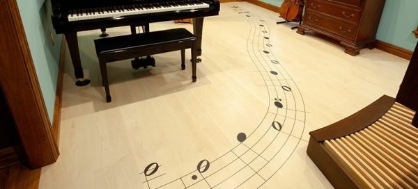
It’s been a few years since we first started hearing about “tools of the future changing the way we work” but this astounding whole-room floor inlay might be the best argument for them yet.

The Shaper Origin

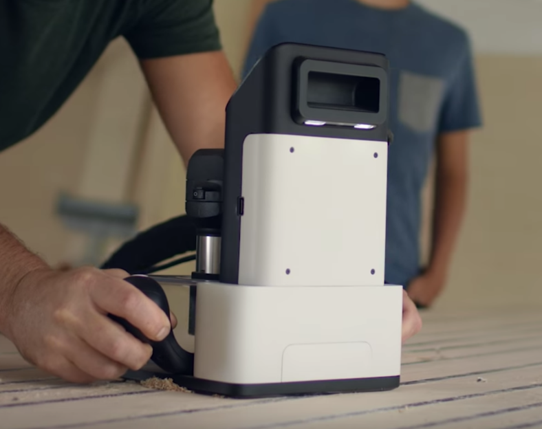
A couple of years ago we wrote a hands-on preview of a unique tool called the Shaper Origin. If a milling machine is classically defined as having a stationary tool head with moving stock, the Origin is the reverse. To use an Origin the user adheres specially marked tape to the stock material, then holds the origin down and moves it much like a hand router.

The Origin has a camera which tracks the fiducial patterns on the tape, allowing it to know its precise position, even across an entire room. The operator sees a picture on the screen of the tool that guides them with superimposed lines, while the tool head makes its own precision adjustments to perfectly cut the design in the X, Y, and Z.

Floor in Progress

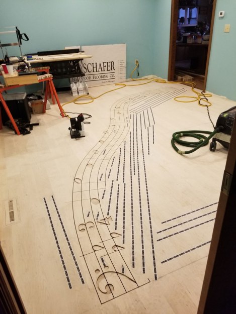
But what do you use a tool like this for? Cutting boards, small tables, and toy blocks are fine examples but don’t highlight any unique features of the tool. Many could just as easily be made using a ShopBot, X-Carve, Carvey, or any of their ilk. What you can’t do with any of those tools (or really anything besides manual labor, endless patience, and master skill) is inlay an entire floor in situ.

[Mark Scheller] (eight time winner of Wood Floor of the Year awards) used an Origin to cut a curvaceous 22 foot long rendition of the first 9 bars of Handel’s Passacaglia into the floor of a lucky homeowner’s music room. Without decades of practice, it’s difficult to imagine doing this any way besides with a Shaper Origin. You can’t put an entire room into a CNC router. The individual floorboards could be cut, but that would be tedious and increasingly difficult as the room gets larger. With the Origin it seems almost trivial. Do the design, place the marking tape, and cut. The same model is used to cut the inlays for a perfect fit. This is an incredible example of a unique use for this unusual tool!

Circuit-Sword Delivers Retro Justice

You can’t search for “retro gaming” without hitting a plethora of single board computers attached to all manner of controls, batteries, etc. Often these projects have an emphasis on functionality above all else but [Kite]’s Circuit-Sword is different. The Circuit-Sword is the heart of a RaspberryPi-based retro gaming machine with an enviable level of fit and finish.

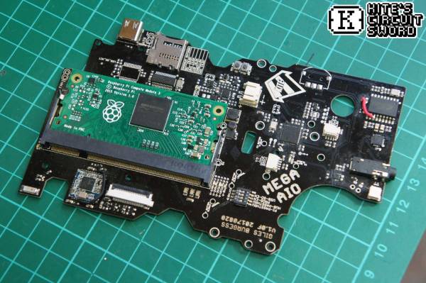
Fundamentally the Circuit-Sword is a single board computer built around a Raspberry Pi Compute Module 3. We don’t see many projects which use a Compute Module instead of the full Pi, but here it is a perfect choice allowing [Kite] to useful peripherals without carrying the baggage of those that don’t make sense for a portable handheld (we’re looking at you, Ethernet). The Circuit-Sword adds USB-C to quickly charge an onboard LiPo (rates up to 1.5A available) and the appropriate headers to connect a specific LCD. The Compute Module omits wireless connectivity so [Kite] added an SDIO WiFi/Bluetooth module. And if you look closely, you may notice an external ATMega mediating a familiar looking set of button and switches.

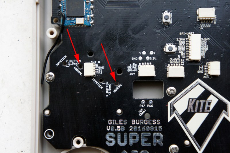
Optional Drill Holes

We think those buttons and switches are the most interesting thing going on here, because the whole board is designed to fit into an original GameBoy enclosure. It turns out replacement enclosures are available from China in surprising variety (try searching for “gameboy housing”) as are a variety of parts to facilitate the installation of different screen options and more. One layer deeper in the wiki there are instructions for case mods you may want to perform to make everything work optimally. The number of possible options the user can mod-in are wide. Extra X/Y buttons? Shoulder buttons on the back? Play Station Portable-style slide joysticks? All detailed. For even more examples, try searching the SudoMod forums. For example, here’s a very visual build log by user [DarrylUK].

The case mod instructions are worth a glance even if you have no intent to build a device. There are some clever techniques to facilitate careful alignment of buttons and accurate hole drilling. Predicting their buyers might want a variety of options, [Kite] added reference drill holes in the PCB for the builder to re-drill for mounting buttons or joysticks. To facilitate adding status LEDs externally there is a tiny PCB jig included. There are even instructions for adding a faux game cartridge for the complete look.

If you want to buy one (we certainly do!) [Kite] does group buys periodically. Check out the wiki for links to the right interest form.

Thanks [Speednut Dave] for the tip!

Color Spaces: The Model At The End Of The Rainbow

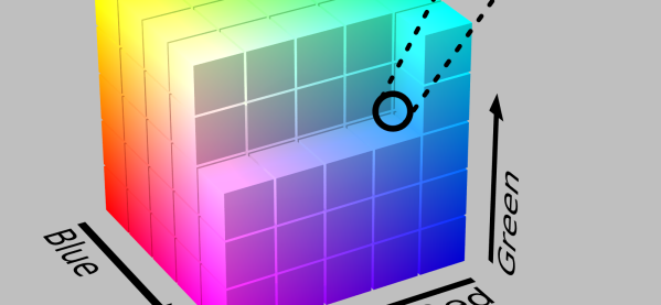
When I learned about colors in grade school everything started with red, yellow, and blue and getting fancier colors was easy. I mixed some blue into my yellow to get green, or into red to get purple, and so on. After painting enough terrifying “art” for my parents, this made intuitive sense. That is until my mind was blown by the revelation that this wasn’t always true! 

To make the same colors with light instead of paint I had to use red, green, and blue, not yellow. It was until much later when trying harness banks of RGB LEDs that this knowledge became useful. I was struggling to make my rogue diodes look quite the way I wanted when I stumbled into the realization that maybe there was another approach. What did the numbers representing R G and B actually mean? Why those parameters? Could there be others? [Elliot Williams] has written about the importance of gamma correction and adjustment for human perception of color, but we can ask a more fundamental question. Why do we represent color this way at all?

Continue reading “Color Spaces: The Model At The End Of The Rainbow”

An LED Effect For Every Occasion

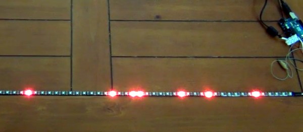
Quality software development examples can be hard to come by. Sure, it’s easy to pop over to Google and find a <code> block with all the right keywords, but having everything correctly explained can be hit or miss. And the more niche the subject, the thinner the forum posts get. Bucking the downward trend [HansLuijten] provides an astoundingly thorough set of LED strip patterns in his comprehensive post titled Arduino LED strip effects.

Don’t let the unassuming title lead you astray from the content, because what’s on offer goes beyond your average beginner tutorial on how to setup a strand of NeoPixels. [HansLuijten] is thorough to a fault; providing examples for everything from simple single color fades and classic Cylon eyes to effects that look like meteors falling from the sky. Seriously! Check out the videos on their webpage. Those chasing lights you see around theater signs? Check. Color twinkle and sparkle? Check. Color wipes and rainbow fades? Check, and check. Continue reading “An LED Effect For Every Occasion”