Manufacturers of low-cost 3D printers that use the masked stereolithography (MSLA) process are able to build their machines so cheaply because they’re using repurposed smartphone or tablet LCD panels to mask off the UV backlight. Considering the quality you get out of even the entry-level MSLA resin printers, we certainly aren’t complaining about this bit of thrift. But as [Jan Mrázek] explains in a recent blog post, there’s certainly room for improvement.
The problem is that those repurposed LCD panels are, as you’d expect, color displays. After all, even the bottom of the barrel mobile devices moved away from monochrome displays decades ago. But in this case, that’s not what you really want. Since the printer operates on a single wavelength of light, the color filters inside the LCD are actually absorbing light that could otherwise be curing the resin. So an MSLA printer with a monochrome screen would use less energy and print faster. There’s only one problem: it’s not very easy to find high-resolution monochrome displays in the year 2020.
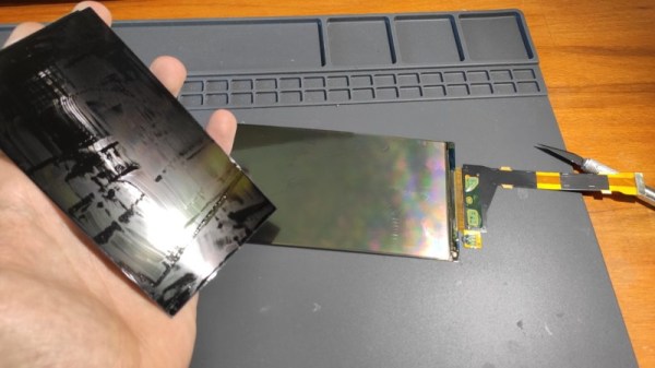
 So [Jan] decided to see if he could take a replacement screen intended for his Elegoo Mars MSLA printer and convert it from color to monochrome by disassembling it and manually removing the color filters. If this sounds a bit crazy, that’s because it is. Turns out taking apart an LCD, modifying its internal layout, and putting it all back together in working order is just as difficult as you’d think.
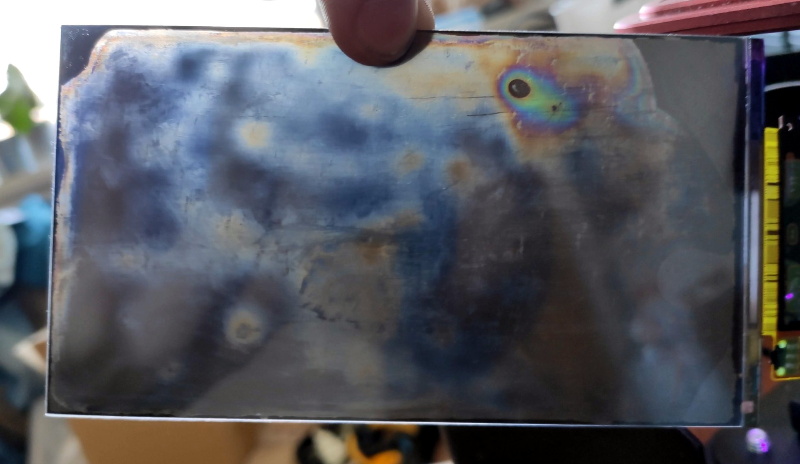
But it was still worth a try. [Jan] pulls the display apart, removes the liquid crystals, scrapes off the color filters, and then puts it all back together again. His first attempt got him a monochrome display that actually worked, but with debris trapped inside the screen, the image was too poor to be useful. He tried again, this time trying harder to keep foreign material out of the crystals. But when he got it back together a second time, he found it no longer functioned. He thinks it’s possible that his attempt to clean up the inside of the display was too aggressive, but really there are so many things that could go wrong here it’s hard to pin down just one.
Long story short, manually creating monochrome displays for low-cost MSLA printers might not be a viable option. Until a better solution comes along, you might be interested in seeing some slightly less invasive ways of improving your resin print quality.