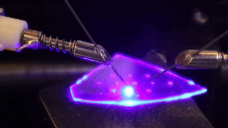
An irregular shard of a crystal wafer is set on a table, with two wire probes contacting it. Between the probes, a bright blue-purple light glows, illuminating the rest of the wafer.

Making LEDs In The Home Fab

Impressive as it most certainly is when an amateur fabricates a semiconductor, most of the projects we’ve seen are more demonstrations than workable chips. [Dr. Semiconductor], however, is going much further with his fabrication process, and is already working on a method to bond chips to printed circuit boards. It’s difficult to align a PCB with the pads on the underside of an opaque silicon wafer, however, so as a trial run he’s made and bonded some transparent LED chips.

The starting material for these chips is a gallium nitride (GaN) LED epiwafer, a stacked structure of n-doped GaN, an indium gallium nitride quantum well layer, and p-doped GaN grown on a sapphire substrate. When current passes through the structure, electrons from the n-doped layer and holes from the p-type layer recombine in the quantum well layer, emitting blue light. To make a functional LED from this, [Dr. Semiconductor] needed to make electrical contacts to both the n-type and p-type layers. Making the n-type contact required cutting through the p-type and quantum well layers.

This would normally be done with reactive ion etching in chlorine, but [Dr. Semiconductor] came up with a new process: a 355-nm ultraviolet etching laser causes GaN to break down into gallium and nitrogen, with the resulting cut being cleaned up by a potassium hydroxide etch. To deposit the contacts themselves, [Dr. Semiconductor] formed a photoresist mask, deposited metal (nickel, silver, and titanium) in a sputtering chamber, and used a developer solution to dissolve the mask and lift off the unwanted metal regions.
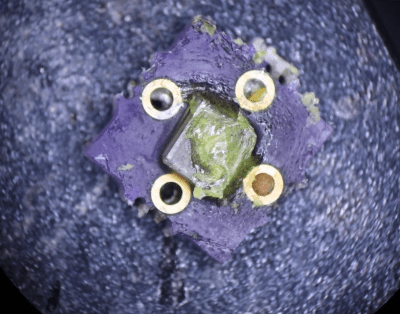
A square, purple PCB is shown under a microscope. The PCB has four vias surrounding a transparent chip, which has a blob of translucent yellow material on top of it.
The LED after bonding and phosphor application.

When [Dr. Semiconductor] applied current between the two contacts, the LED glowed bright blue. The next step was to mount it to a PCB; to do so, he first sliced the wafer into individual LED chips with the ultraviolet laser. He then electroplated indium bumps onto a printed circuit board, positioned the chip above these bumps, added some rosin flux, and melted the indium bumps. This soldered the chip to the board and let the board power the LED.

Like most commercial LEDs, these were blue; most LED assemblies additionally include a phosphor layer which absorbs blue light and emits another color. To create a white LED, for example, [Dr. Semiconductor] mixed cerium-doped yttrium aluminium garnet phosphor power with clear silicone and spread it over the LED. This absorbs some of the blue light and emits yellow light, and the resulting mixture of blue and yellow light looks white to human eyes.

We’ve previously covered some of the history of LEDs and the phosphors which make them useful. This seems to be the first inorganic LED we’ve seen, but we’ve also seen a few homemade OLEDs.

Thanks to [SpuriousIndices] for the tip!
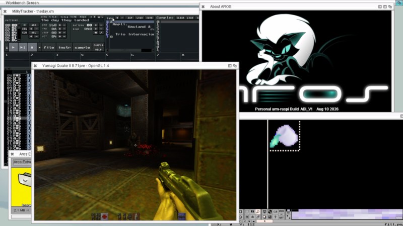
Amiga-Inspired AROS Goes Bare Metal On Raspberry Pi

There’s no actual data, but if we had to guess the least-favourite Disney movie of former Amiga owners would have to be Frozen, because none of them will ever be able to “Let it Go”. The Amiga-derived AROS Research Operating System has just been ported to boot bare-metal on the Raspberry Pi, in both 32-bit and 64-bit versions. Yes, there’s a 64-bit Amiga-compatible OS that runs on ARM. It truly is a time of wonders.

AROS has already been ported to a number of platforms. Besides x86, there’s a PPC port that provided a lot of code to the MorphOS, which you can read about here, and a back-port that brings AROS back to original Amiga 68k hardware. There is even a build for RISC V.

AROS developers are making sure that Amiga legacy isn’t stuck on any given hardware, so they never have to let it go. So while not totally out of left field, this development is “pretty nifty” both in that it gives another ultralight operating system for the Pi, with boot times to rival RiscOS, and another platform for ex-Amiga users to play with that isn’t 40 years old. Previously if you wanted to run AROS on a Pi it was virtualized in Linux, making it similar to all other Amiga emulators.

While some software has been recompiled for ARM, the available software isn’t as full-featured as x86, but that’s almost certain to change as time goes on. It’s early days yet and this build is very much a work in progress. Likewise we expect support for other Pi boards to expand, as while right now the target is the Pi3, the forum threads include discussion of the Pi4 and even Zero2W.

You can check the port out in action in a video by [Dan Wood] embedded below, sent to us by tipster [Stephen Walters]. Thanks [Stephen]!

We have featured AROS once before, thought it’s been a while.

Continue reading “Amiga-Inspired AROS Goes Bare Metal On Raspberry Pi”

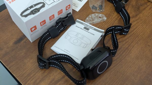
Bluetooth Shock Collar Keeps Wearer On Task

Like a lot of us [Liam Kloppers] had a problem with doomscrolling. Unwilling to go cold-turkey because he does find some utility in social media. He tried a number of things before deciding to say “Screw it” and just go full Pavlov on himself with some old-fashioned classical conditioning. Who needs willpower when you have electric shocks to dissuade you?

The key here was finding an electric-shock dog collar that could be controlled via a smartphone application, which meant he could reverse-engineer its Bluetooth protocol and get it linked up to his own software. The initial implementation ties his quick-and-dirty Python control program with a web server living on his laptop, which he’s configured MacroDroid to call on when his personal criterion for ‘doomscrolling’ is met.

With the shock collar wrapped around his leg, [Liam] was ready to test. It turns out dogs are a lot tougher than people, because even when set to a low level, the shock from the device made him toss his phone across the room and had him hesitant to even pick it up again.

Since he couldn’t bring himself to put the shock collar back onto his leg, he’s now thinking of an audible alarm, something we’ve seen work before. If you’re as unhappy with your habits as [Liam], perhaps consider a device like Commodore’s social-media-free phone before resorting to self-electrocution.

So, You Found A Foden Steam Lorry In A Field. What Next?

It’s quite likely that many readers will have harbored dreams of owning, or at least driving, a steam engine of some kind. [James Hervey-Bathurst] was lucky enough to do so in a time when it was still possible to find scrap steam-powered machinery for restoration, and at the recent Electromagnetic Field event in the UK he took the time to describe his journey from finding an abandoned steam lorry in a Buckinghamshire field in 1975, to a few years later, taking it to the road.

The talk starts with the story of its retrieval, then the long process of rebuilding, and finally its first run. He’s the owner of Eastnor Castle, the ancestral pile that serves as venue for EMF Camp, so we’re guessing that having somewhere spacious for such a project must have helped. Along the way, we get a comprehensive run through the workings of a 1920s steam vehicle, from its double-expansion compound engine to its three-speed gearbox, stopping for small details like its injectors, and a curious exhaust steam heater designed to reduce the clouds of visible steam.

Most of us will never get the chance to take the wheel of a Foden such as this one, but at least we’ve had a chance for a closer look thanks to EMF. The full video is below the break, meanwhile if you’d like more on steam injectors we have you covered.

Continue reading “So, You Found A Foden Steam Lorry In A Field. What Next?”

Turning Corroded, Bug-Loving WiiMotes Into A Working One

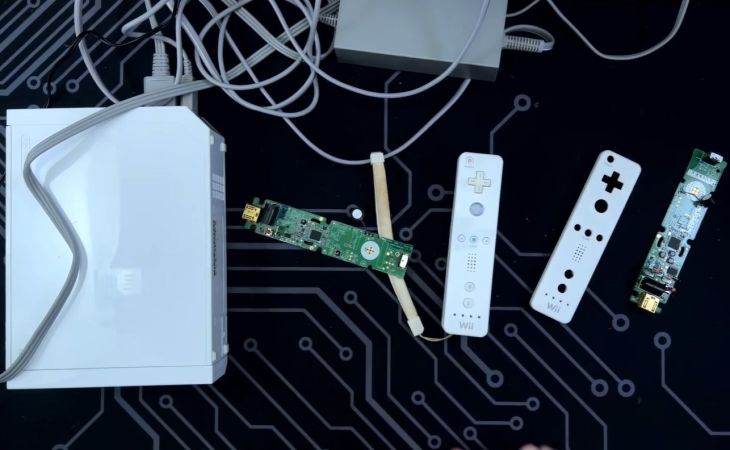
A time-honored tradition in the electronics repair business is to make many into one, specifically a stack of broken devices into one that works. So too with a triplet of heavily corroded and bug-infested WiiMote controllers that [eWastelander] dug out of a box of e-waste. After suffering abuse like leaving in leaky alkaline cells, bugs and general corrosion the task was to see whether at least one working WiiMote could be assembled from these three. (Video, embedded below.)

Adding to the fun was that the PCBs in these WiiMotes spanned at least two hardware revisions, and on one board the battery corrosion had caused an IC to fall off. After an initial assessment, neutralizing the battery acid and a deep clean of all the disassembled parts, it was time to give it a shot at reassembly into something resembling a Wii controller you could use and even want to touch without washing your hands afterwards.

Ultimately at least one working WiiMote was put together, with still an open question whether the remaining two  units in much worse conditions could be revived in some way. An interesting idea here is to use the WiiMote shells for a custom OpenMote board, which replaces the guts with an ESP32-S3-based system for more general non-Wii things around the house.

Continue reading “Turning Corroded, Bug-Loving WiiMotes Into A Working One”

An Atari Desktop On A Sega

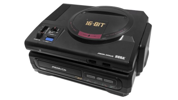
Over recent years there have been a range of classic 16-bit consoles coaxed into running familiar operating systems, with -nommu Linux being a favourite. But the 16-bit era had its own operating systems of note, and [1d4r3k] has brought one of them to a console that fit very much into a different 16-bit camp. It’s Atari’s TOS, on a Sega Mega CD.

We should in all fairness start by saying it’s not “real” TOS, but EmuTOS, an open-source drop-in replacement. So far it supports a serial keyboard device, a printer, and sound, and it mounts the CD or cartridge it booted from, a RAMdisk, internal backup RAM, and cartridge save RAM. We’re told in the tip email that there’s also been some work porting GEOS to the platform, and thus the GEOS software suite may be ported to it.

Sadly there are no images, so we can’t see it working, but trying it looks to be as straightforward as burning aan ISO or flashing a cartridge if you have the original hardware. We have no idea as to whether it would be any use given the specs of the Sega, but given that TOS ran on Ataris without a lot of RAM we suspect it might be. Meanwhile, here’s a Megadrive/Genesis running Linux.

Header: 軍事用懐中電灯, CC BY-SA 4.0.

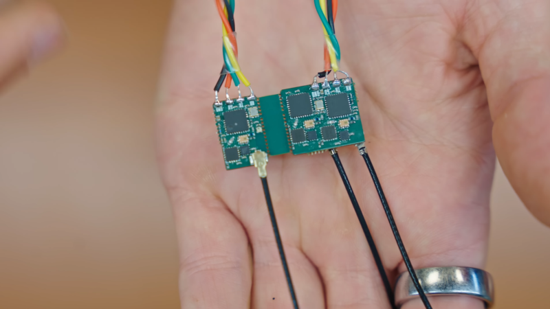
A man's hand is shown holding two small circuit boards, joined together by a central bridge. Each circuit board is connected to four wires and a coaxial antenna cable.

Open-Source ExpressLRS Receiver Reaches For Range

Drone control links are, from a radio signals perspective, nothing short of amazing: using a transmitter capable of transmitting, at most, one watt, a protocol such as ExpressLRS (ELRS) can control a drone over 100 kilometers away. [Stan], who has been building a drone electronics stack from scratch, recently designed four ELRS receivers and went over the principles behind their incredible range.

Up to a certain point, the simplest way to increase a radio’s range is to lower the frequency; lower radio frequencies penetrate better through most materials and don’t attenuate as quickly with distance. However, although ELRS can use 900 MHz bands, [Stan]’s receivers primarily use 2.4 GHz. The major improvement is in modulation: unlike other control protocols, which mostly use frequency modulation, or Wi-Fi, which uses phase and amplitude modulation, ELRS uses Chirp Spread Spectrum modulation. This has a low data rate, but it’s very reliable; every bit is transmitted as a chirp – a linearly rising radio tone – and the data is encoded in the chirp’s starting frequency. To decode this, the receiver multiplies it with an inverse chirp, then takes a fast Fourier transform, revealing the starting frequency. This process has an equivalent gain of 24 dB, which is enough to let it decode signals even below the receiver’s noise floor.

The hardware [Stan] designed to implement this was comparatively simple, just an ESP32 microcontroller, an SX1281 radio chip, and a few peripherals. All four receivers worked in 2.4 GHz, but two had additional 900 MHz antennas. Against RF design convention, one of the receivers used a via to connect the antenna. This would normally cause a significant impedance mismatch, but since there were enough ground-plane vias nearby, the current return path was barely affected; the receiver’s performance hardly changed. In one test, all four receivers maintained a connection at more than five kilometers, despite a forest blocking the signal’s path.

We previously covered ExpressLRS when it was still an emerging technology. To get this kind of range, it builds on LoRa technology, which has reached some impressive distance records.

Thanks to [Keith Olson] for the tip!