Being an early adopter is great if you enjoy showing off new gadgets to your friends. But any new technology also brings the risk of ending up at the wrong side of a format war: just ask anyone who committed to HD-DVD fifteen years ago. If, on the other hand, you were among the few who invested in CD-ROM when it was first released in the mid-1980s, you definitely made the right choice when it came to storage media. However, it was a bit of a different story for the interface that hooks up the CD drive to your computer, as [Tech Tangents] found out when he managed to get his hands on a first-generation CM100 drive. (Video, embedded below.)
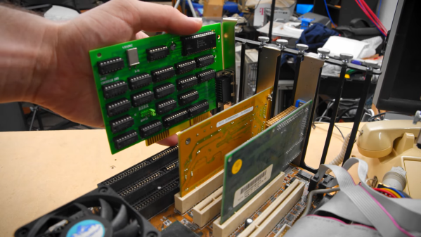
That wonderful piece of 1985 technology is not much smaller than the IBM PC it was designed to connect to, and it originally came with its own CM153 ISA interface card. But while most eBay sellers recognized the historic value of a pioneering CD-ROM drive, the accompanying PC was typically a dime-a-dozen model and was thrown out with the rare interface card still inside. Even after searching high and low for over a year, the only information [Tech Tangents] could find about the card was a nine year old YouTube video that showed what the thing looked like.
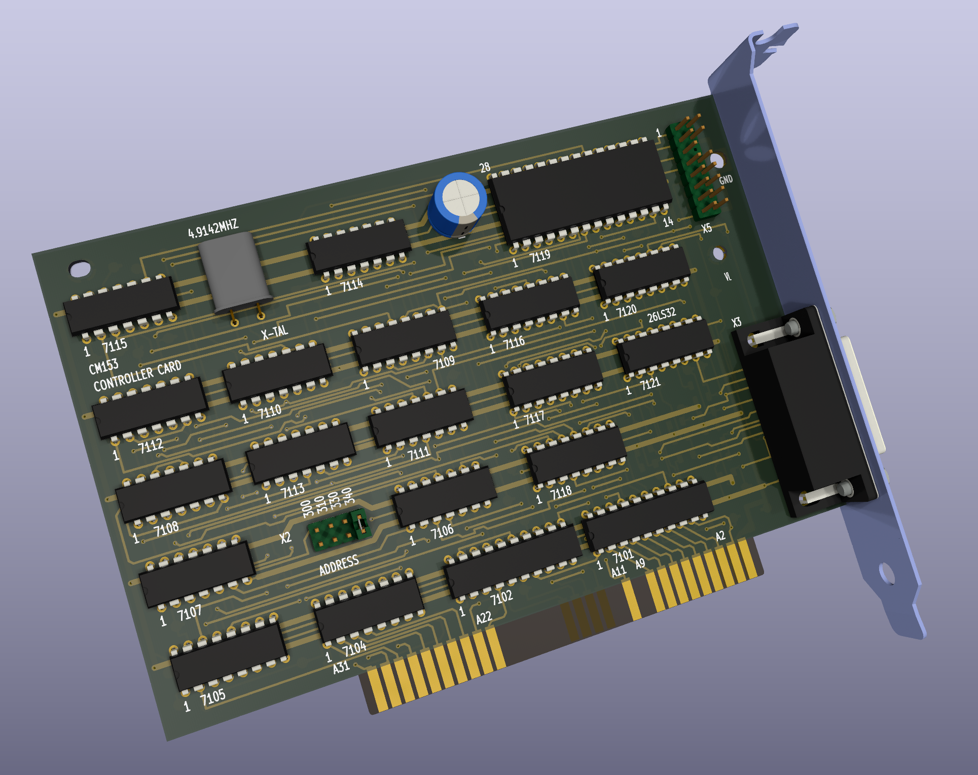 Luckily, the maker of that video was willing to take high-resolution pictures of the card, which allowed [Tech Tangents] to figure out how it worked. As it turned out, the card was entirely made from standard 7400 series logic chips as well as an 8251 USART, which meant that it should be possible to design a replacement simply by following all the traces on the board. [Tech Tangents] set to work, and after a few weeks of reverse-engineering he had a complete schematic and layout ready in KiCAD.
After the PCBs were manufactured and populated with components, it was time to test the new card with the old drive. This wasn’t a simple process either: as anyone who’s tried to get obscure hardware to work in MS-DOS will tell you, it involves countless hours of trying different driver versions and setting poorly documented switches in CONFIG.SYS. Eventually however, the driver loaded correctly and the ancient CD-ROM drive duly transferred the files stored on a Wolfenstein 3D disk.
If you’re lucky enough to own a CM100 or a similar drive from that era, you’ll be happy to know that all design files for the CM153 clone are available on GitHub. This isn’t the first time someone has had to re-create an interface board from pictures alone: we’ve seen a similar project involving a SCSI card for a synthesizer. Thanks for the tip, [hackbyte]!
Continue reading “Reverse-Engineering An ISA Card To Revive An Ancient CD-ROM Drive”

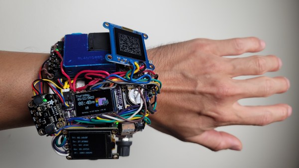
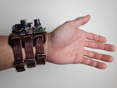 [Rob] has been focusing on day-to-day usability first and foremost, with pleasantly clicky encoders, impeccable performance of its watch duty, unparalleled expandability, and comfortable wrist fit — it provides a feeling no commercial wearable could bring.