Robot Moves In Any Direction On Ball Wheels

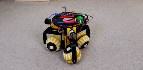
The ability to move in any direction and turn on the spot is a helpful feature on robots that operate indoors around other objects. [James Bruton] demonstrated one possible solution in the form of a robot chassis that can move in any direction with three ball-shaped wheels.

The video after the break is part two of this series. Part one covered the ball wheels themselves, consisting of a pair of half-spheres that can rotate independently with a small roller in the center of each and a driven shaft through the center of the sphere. Three of these are arranged at 120° intervals around the center of the robot, with the main shafts driven by geared DC motors using belts. To move in a straight line some basic trigonometry is used to calculate the required relative speed of each wheel. An Arduino Mega is used to do the necessary calculation when receiving input from the wireless controller.

The motion is remarkably smooth, and we’d be interested to see how it compares with Mecanum and Omniwheels. It seems like the perfect platform for [James]’ Really Useful Robot. He hinted that he might mount a trash bin on it in the future. We would love to see an automatic trash-catching robot, similar to [StuffMadeHere]’s robotic basketball hoop. Continue reading “Robot Moves In Any Direction On Ball Wheels”

Living Robots: Revisiting BEAM

You’re hit by the global IC shortage, reduced to using stone knives and bearskins, but you still want to make something neat? It’s time to revisit BEAM robots.

Biology, electronics, aesthetics, and mechanics — Mark Tilden came up with the idea of minimalist electronic creatures that, through inter-coupled weak control systems and clever mechanical setups, could mimic living bugs. And that’s not so crazy if you think about how many nerves something like a cockroach or an earthworm have. Yet their collection of sensors, motors, and skeletons makes for some pretty interesting behavior.

My favorite BEAM bots have always been the solar-powered ones. They move slowly or infrequently, but also inexorably, under solar power. In that way, they’re the most “alive”. Part of the design trick is to make sure they stay near their food (the sun) and don’t get stuck. One of my favorite styles is the “photovore” or “photopopper”, because they provide amazing bang for the buck.

Back in the heyday of BEAM, maybe 15 years ago, solar cells were inefficient and expensive, circuits for using their small current were leaky, and small motors were tricky to come by. Nowadays, that’s all changed. Power harvesting circuits leak only nano-amps, and low-voltage MOSFETs can switch almost losslessly. Is it time to revisit the BEAM principles? I’d wager you’d put the old guard to shame, and you won’t even need any of those newfangled microcontroller thingies, which are out of stock anyway.

If you make something, show us!

Solar Plane Is Like One Big Flying Solar Panel

Solar-powered plane concepts typically focus on high-efficiency glider-type designs, so as to make the best possible use of the limited power available from the sun. [rctestflight] wanted to try a different school of thought, instead building a relatively inefficient plane that nonetheless packed a huge amount of solar panels on board.

The plane consisted of a pizza-box style design, with a simple foam rectangular wing that was absolutely covered in solar panels. The plane was controlled with an off-the-shelf autopilot, and fitted with cheap, no-brand MPPT modules to handle charging the batteries. The plane faced difficulties in flight, most often with stability, which led to the autopilot getting the plane lost on one occasion. However, one flight was achieved with a full one hour and thirty minute duration, indicating the solar panels were helping to extend flight times beyond what was capable with batteries alone.

Further research on the ground showed that the cheap MPPT modules were wasting power, and there was more to be had. A better MPPT module was subbed in and showed that the panels could generate up to 5 amps under good conditions, while the plane only needed roughly 4.2 amps to fly. This would allow for indefinite flight in sunny conditions, though probably would not allow enough energy to be banked to fly 24 hours round the clock due to the lack of power at night.

We’ve followed [rctestflight]’s solar plane experiments for a while now, and can’t wait to see the next iteration. Video after the break.

Continue reading “Solar Plane Is Like One Big Flying Solar Panel”

3D Printed Flip Dots

Displays have come a long way in the last few decades, but none can deliver the mesmerizing visual and audio experience of a large flip dot display. Both old panels and new panels can be expensive and difficult to source, so [Larry Builds] made his own flip dots with the help of 3D printing.

Flip dots are driven by a pair of electromagnetic posts that attract or repel a magnet embedded in the dot, and [Larry Builds] version is no different. For the electromagnets, he used M3 threaded rod with enamel wire wound around them using a drill. At first, he used a large magnet in the center of the 3D printed dot, but the magnetic field was large and strong enough to flip the surrounding dots in an array. He then changed the design to a small 4 mm diameter magnet in the edge that aligns directly with the electromagnets. This design looks very similar to those used by Breakfast for their massive installations. By modifying electromagnets and adding spacers around the magnets, he was able to reduce the operating current from 2 A to below 500 mA. [Larry Builds] also breadboarded a basic driver circuit consisting of H-bridges multiplexed to rows and columns with diodes.

We will be keeping a close eye on this project, and we look forward to seeing it evolve further. It’s definitely on our “things to build” list. We’ve embedded multiple videos after the break showing the progress thus far.

We’ve covered several interesting flip dot projects, including a water level indicator that doesn’t use any electronics and another that is crocheted. Continue reading “3D Printed Flip Dots”

Build A New ZX81

[Retro Shack’s] ZX81 died, and while he tried to figure out the fix, he decided to build a new one. Of course, building a circa-1980-something computer from new parts is a bit daunting. Unless you start with an existing design that has it all ready to put together.

The PCB looks great and we like that the silkscreen shows acknowledgments of projects that helped the designer, [Alejandro Sebastian]. The case is, of course, 3D printed. At first, the power LED didn’t work, but voltages looked correct and the board powered up.

Continue reading “Build A New ZX81”

Web Assembly, Music Synthesis, And The Beauty Of Math

The electronics hobby has changed a lot since the advent of the microprocessor. Before that — and with the lack of large-scale integrated circuits — projects in magazines tended to be either super simple or ultra complex. However, one popular type of project dealt with music synthesis. Fairly simple circuits could combine to make a complex synthesizer so it was sort of the best of both worlds. Nowadays, you are more likely to tackle a music synthesizer in software like [Tim] did when he created Abelton in Web Assembly and C++. Along the way, he learned a lot about the relationship between math and music.

[Tim] covers what he learned about the Nyquist theorem and how to keep synthesis data flowing in real time with buffers. However, there are some problems trying to do all this in a cross-browser context. The AudioWorklet class appears to have widespread support, though, and [Tim] managed to get that working.

Continue reading “Web Assembly, Music Synthesis, And The Beauty Of Math”

JTAG Hat Turns Raspberry Pi Into A Networked Debugger

Over the last year or so we’ve noticed a definite uptick in the number of folks using OpenOCD on the Raspberry Pi. It’s a cheap and convenient solution for poking around with various microcontrollers and embedded devices, but not always the most elegant. Looking to improve on the situation somewhat, [Matthew Mets] has been working on a purpose-built JTAG Hat to clean things up a bit.

Onboard level shifters allow you connect to JTAG and SWD interfaces from 1.8 to 5 V, and if you power the target device from the Pi itself, there’s even support for measuring the voltage and current. To connect up to your target, the open hardware board features a “legacy” pin header perfect for jumper wires, as well as a dedicated 10-pin Cortex Debug Connector. Whether you spin up your own or buy one assembled, it certainly looks like a tool worth having around if you often find yourself working with the appropriate chips.

In addition to the design files for the hardware, [Matthew] has also provided some nice documentation on how to get the software side of things up and running. Starting with a blank SD card, it walks you through the initial setup of the Raspberry Pi all the way through the installation and configuration of a patched version of OpenOCD designed to support the JTAG Hat.

If you spend more time working with 8-bit AVR chips, don’t worry. Last year we covered a similar project to turn everyone’s favorite Linux SBC into an all-in-one microcontroller development powerhouse.