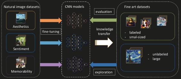
In 2019, using AI to evaluate artwork is finally more productive than foolish. We all hope that someday soon our Roomba will judge our living habits and give unsolicited advice on how we could spruce things up with a few pictures and some natural light. There is already an extensive amount of Deep Learning dedicated to photo recognition but a team in Croatia is adapting them for use on fine art. It makes sense that everything is geared toward cameras since most of us have a vast photographic portfolio but fine art takes longer to render. Even so, the collection on Wikiart.org is vast and already a hotbed for computer classification work, so they set to work there.
As they modify existing convolutional neural networks, they check themselves by comparing results with human ratings to keep what works and discard what flops. Fortunately, fine art has a lot of existing studies and commentary, whereas the majority of photographs in the public domain have nothing more than a file name and maybe some EXIF data. The difference here is that photograph-parsing AI can say, “That is a STOP sign,” while the fine art AI can say, “That is a memorable painting of a sign.” Continue reading “AI And Art Appreciation”→
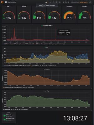
Commuting through the urban sprawl of a 21st century city brings exposure to significant quantities of pollution. For a Medway Makers member that meant the Isle of Dogs, London, and a drive through the Blackwall Tunnel under the Thames. When you can taste the pollution in the air it’s evident that this isn’t the best environment to be in, but just how bad is it? Time to put together an environmental monitoring and recording rig.
Into the build went an ESP32 module, an SPS30 particulate sensor, an MH-Z19 CO₂ sensor, an HTU21D temperature and humidity sensor, and a uBlox NEO 6M GPS module. The eventual plan is to add an SD card for data logging, but in the absence of that it connects to a Raspberry Pi running Grafana over InfluxDB for data analysis. The result provides a surprising insight into the environmental quality of not just a commute but of indoor life. We’re sorry to say that they don’t seem to have posted any of the code involved onto the Medway Makers writeup, though we hope that’s an oversight they’ll rectify by the time this has gone live.
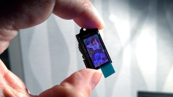
Hackers have a multitude of skills, many are well-versed in the ways of all things that blink and flash. These abilities have often be applied to the field of jewelry and human adornment, and many LEDs have been employed in this work. [Deshipu] has been attempting something a touch different however, by constructing a tiny TFT pendant.
The basic idea is not dissimilar from those USB photo keychains of recent history. A SAMD21 Cortex M0+ serves as the brains of the operation, with the tiny microcontroller being soldered to a custom PCB that makes up the body of the pendant. A ST7735S TFT LCD screen is then attached to act as the display. Charging and delivery of images is done over USB, which can be handled natively by the SAMD21.
Currently, the pendant is capable of displaying 16-color BMPs, with the intention to create a converter for animated GIFs in the pipeline. Potential upgrades also involve creating a larger battery pack to sit behind the wearer’s neck, as currently the device has just 8 mAh to work with.
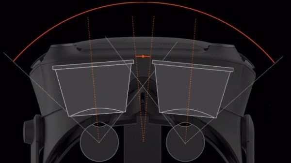
VR headsets have been seeing new life for a few years now, and when it comes to head-mounted displays, the field of view (FOV) is one of the specs everyone’s keen to discover. Valve Software have published a highly technical yet accessibly-presented document that explains why Field of View (FOV) is a complex thing when it pertains to head-mounted displays. FOV is relatively simple when it comes to things such as cameras, but it gets much more complicated and hard to define or measure easily when it comes to using lenses to put images right up next to eyeballs.
Simulation of how FOV can be affected by eye relief [Source: Valve Software]The document goes into some useful detail about head-mounted displays in general, the design trade-offs, and naturally talks about the brand-new Valve Index VR headset in particular. The Index uses proprietary lenses combined with a slight outward cant to each eye’s display, and they explain precisely what benefits are gained from each design point. Eye relief (distance from eye to lens), lens shape and mounting (limiting how close the eye can physically get), and adjustability (because faces and eyes come in different configurations) all have a role to play. It’s a situation where every millimeter matters.
If there’s one main point Valve is trying to make with this document, it’s summed up as “it’s really hard to use a single number to effectively describe the field of view of an HMD.” They plan to publish additional information on the topics of modding as well as optics, so keep an eye out on their Valve Index Deep Dive publication list.
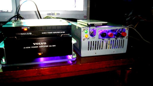
The common automotive scrap yard is a land of plenty for the enterprising hacker., where many items that would be prohibitively expensive elsewhere can often be had for a song. This isn’t just limited to strictly automotive parts either, as the modern vehicle is full of all kinds of hardware. [Nikita] managed to salvage a pair of audio amplifiers from an old Volvo, and put them to good use. It’s a great idea if you’re looking for cheap audio hardware!
The amplifiers are from a Volvo 760 made in 1984. There’s one rated at 40 watts per channel, and a smaller device rated at 25 watts per channel – likely to drive the front and rear speakers from separate amps. The amplifiers take 12 volts nominally, as one would expect. After some initial testing with a car battery and unsticking old relays, things began to crackle into life.
With the hardware now functioning, it was simply a case of bolting the amplifiers into a frame, hooking them up to a converted ATX power supply, and wiring up some connectors for speakers and audio input. With a few bits and pieces invested, [Nikita] now has a good quality amplifier to run audio in the workshop.
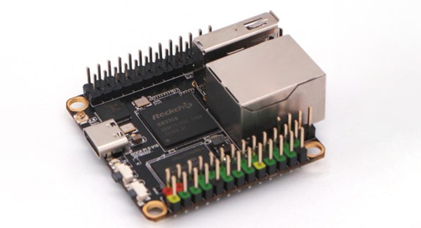
Single board computers are great, but what we really need are cheap single board computers. Running Linux on anything isn’t as good as running Linux on everything, and all that. To that end, here is the Rock Pi S, a $10 single board computer with Ethernet, WiFi, and it costs $10.
This one comes from the boffins at Radxa, already behind the footnote-worthy Rock Pi 4, a single board computer that appears to be heavily derived from the Raspberry Pi but with a 4 in the name so it’s obviously better. It also has 4 GeeBees of RAM, so it’s got that going for it too. Their latest product is the Rock Pi S, a board that seems as though it’s taking inspiration from the C.H.I.P.. The biggest selling point is of course the price: $10 for the version with 256MB of RAM and without WiFi or Bluetooth. Various other incarnations exist with permutations of 256MB or 512MB of RAM, and with or without WiFi and Bluetooth. The highest spec variant costs $16, but is sold out at the moment.
This tiny little single board computer fills a need in the marketplace; the Raspberry Pi Zero is cheap and small when it’s available, but sometimes you need Ethernet for various reasons and a real USB A port is great to have. We’re looking forward to the builds this tiny board enables and all the fantastic creations that will come from a community so very interested in single board computers.
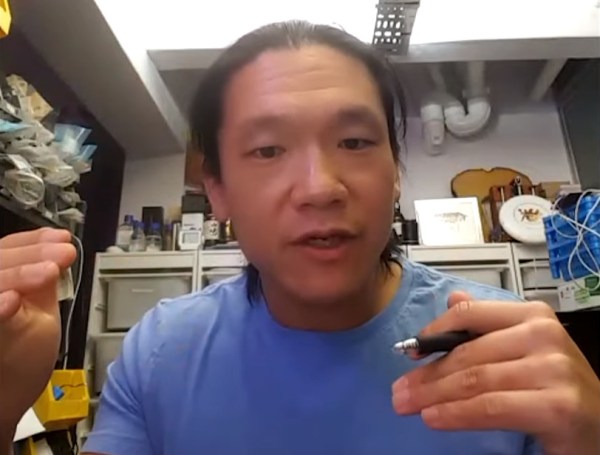
Andrew “Bunnie” Huang’s mentor session for the Hackaday Prize shows off the kind of experience and knowledge hard to come by unless you have been through the hardware development gauntlet countless times. These master-classes match up experts in product development with Prize entrants working to turn their projects into products. We’ve been recording them so that all may benefit from the advice and guidance shared in each session.
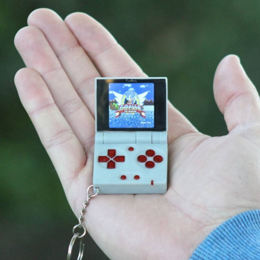
The appealing little FunKey pocket gaming platform.
Bunnie is someone who is already familiar to most Hackaday readers. His notoriety in our community began nearly two decades ago with his work reverse engineering the original Microsoft X-box, and he quickly went on to design (and hack) the Chumby Internet appliance, he created the Novena open-source laptop, and through his writing and teaching, he provides insight into sourcing electronic manufacture in Shenzhen. He’s the mentor you want to have in your corner for a Hackaday Prize entry, and that’s just what a lucky group had in the video we’ve placed below the break.
While this session with Bunnie is in the bag it’s worth reminding you all that we are still running mentor sessions for Hackaday Prize entrants, so sign up your entry for a chance to get some great feedback about your project.
The first team to meet with Bunnie are FunKey, whose keychain Nintendo-like handheld gaming platform was inspired by a Sprite_tm project featuring a converted novelty toy. The FunKey team have produced a really well-thought-out design that is ready to be a product, but like so many of us who have reached that point they face the impossible hurdle of turning it into a product. Their session focuses on advice for finding a manufacturing partner and scaling up to production.
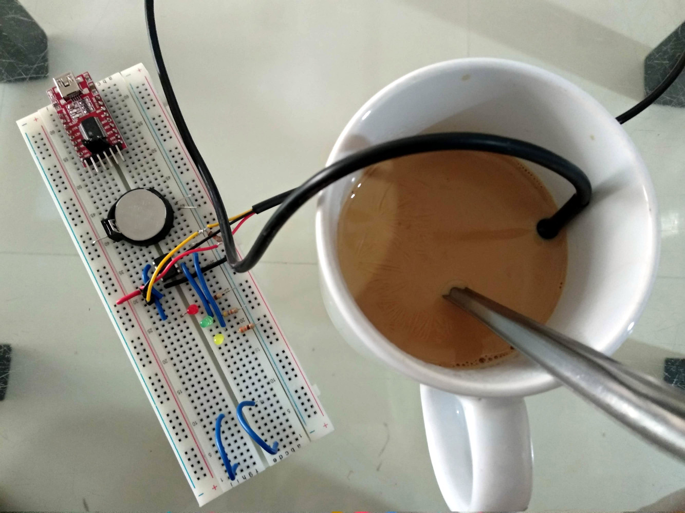
A prototype HotorNot Coffee Stirrer, showing their problem of having to maintain food-safe components.
HotorNot Coffee Stirrer is trying to overcome a problem unique to their food-related project. A hot drink sensor that has to go in the drink itself needs to be food safe, as well as easy enough to clean between uses. A variety of components are discussed including a thermopile on a chip that has the advantage of not requiring contact with the liquid, but sometimes the simplest ideas can be the most effective as Bunnie reminds us that a cheap medical thermometer teardown can tell us a lot about appropriate parts for this application.
The idea behing PhalangePad is an attractive one, but making those sensors reliable is no trivial eercise.
It’s another component choice problem that vexes PhalangePad, an input device that relies on the user tapping the inside of their fingers with their thumb. It’s a great idea, but how should these “keypresses” be detected? Would you use a capacitive or magnetic sensor, a force sensitive resistors, or maybe even machine vision? Here Bunnie’s encyclopaedic knowledge of component supply comes to the fore, and the result is a fascinating insight into the available technologies.
We all amass a huge repository of knowledge as we pass through life, some of the most valuable of which is difficult to pass on in a structured form and instead comes out as incidental insights. An engineer with exceptional experience such as Bunnie can write the book on manufacturing electronics in China but still those mere pages can only scratch the surface of what he knows about the subject. There lies the value of these mentor sessions, because among them the gems of knowledge slip out almost accidentally, and if you’re not watching, you’ll miss them.

 Commuting through the urban sprawl of a 21st century city brings exposure to significant quantities of pollution. For a Medway Makers member that meant the Isle of Dogs, London, and a drive through the Blackwall Tunnel under the Thames. When you can taste the pollution in the air it’s evident that this isn’t the best environment to be in, but just how bad is it? Time to put together