By now we should all be used to the astonishing variety of CPUs that have come our way created from discrete logic chips. We’ve seen everything from the familiar Von Neumann architectures to RISC and ever transport-triggered architecture done in 74 TTL derivatives, and fresh designs remain a popular project for many people with an interest in the inner workings of a computer.
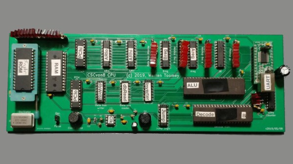
[Warren Toomey]’s CSCvon8 is an interesting machine that implements an 8-bit computer with a 64-bit address space using only 17 chips, and without resorting to any tricks involving microcontrollers. It implements a fairly conventional Von Neumann architecture using TTL with a couple of tricks that use modern chips but could have been done in the same way in decades past. Instruction microcode is stored in an EEPROM, and the ALU is implemented in a very large EPROM that would probably once have been eye-wateringly expensive. This in particular removes many discrete TTL chips from the total count, in the absence of the classic 74181 single-chip part. To make it useful there is 32k each of RAM and EEPROM, and also a UART for serial access. The whole is brought together on a neat PCB, and there is a pile of demo code to get started with. Everything can be found in the project’s GitHub repository.
At the start of this article we mentioned a couple of unconventional TTL CPUs. The transport triggered one we featured in 2017, and the RISC one is the Gigatron which has appeared here more than once.