Have you ever wished you could see in the RF part of the radio spectrum? While such a skill would probably make it hard to get a good night’s rest, it would at least allow you to instantly see dead spots in your WiFi coverage. Not a bad tradeoff.
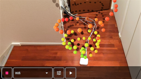
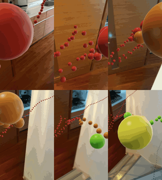 Unwilling to go full [Geordi La Forge] to be able to visualize RF, [Ken Kawamoto] built the next best thing – an augmented-reality RF signal strength app for his smartphone. Built to aid in the repositioning of his router in the post-holiday cleanup, the app uses the Android ARCore framework to figure out where in the house the phone is and overlays a color-coded sphere representing sensor data onto the current camera image. The spheres persist in 3D space, leaving a trail of virtual breadcrumbs that map out the sensor data as you warwalk the house. The app also lets you map Bluetooth and LTE coverage, but RF isn’t its only input: if your phone is properly equipped, magnetic fields and barometric pressure can also be AR mapped. We found the Bluetooth demo in the video below particularly interesting; it’s amazing how much the signal is attenuated by a double layer of aluminum foil. [Ken] even came up with an Arduino with a gas sensor that talks to the phone and maps the atmosphere around the kitchen stove.
The app is called AR Sensor and is available on the Play Store, but you’ll need at least Android 8.0 to play. If your phone is behind the times like ours, you might have to settle for mapping your RF world the hard way.
Continue reading “Smartphone App Uses AR To Visualize The RF Spectrum”

