Robots have certainly made the world a better place. Virtually everything from automobile assembly to food production uses a robot at some point in the process, not to mention those robots that can clean your house or make your morning coffee. But not every robot needs such a productive purpose. This one allows you to punch the world, which while not producing as much physical value as a welding robot in an assembly line might, certainly seems to have some therapeutic effects at least.
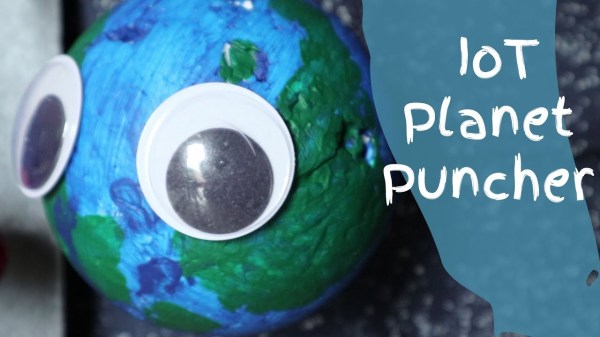
The IoT Planet Puncher comes to us from [8BitsAndAByte] who build lots of different things of equally dubious function. This one allows us to release our frustration on the world by punching it (or rather, a small model of it). A small painted sphere sits in front of a 3D-printed boxing glove mounted on a linear actuator. The linear actuator is driven by a Raspberry Pi. The Pi’s job doesn’t end there, though, as the project also uses a Pi camera to take video of the globe and serve it on a webpage through which anyone can control the punching glove.
While not immediately useful, we certainly had fun punching it a few times, and once a mysterious hand entered the shot to make adjustments to the system as well. Projects like this are good fun, and sometimes you just need to build something, even if it’s goofy, because the urge strikes you. Continue reading “Punch The World With A Raspberry Pi”