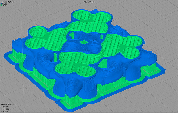
In the practical world we live in, PCBs are often rectangles (or rectangles with rectangles, it’s just rectangles all the way down). When a designer goes to schematic capture things are put down on nice neat grid intersections; and if there isn’t a particular demand during layout the components probably go on a grid too. Routing even the nastiest fractal web of traces is mostly a matter of layers and patience. But if the layout isn’t being done in a CAD tool and needs to be hand assembled free-form this isn’t always as simple. [M Rule] had this very problem and discovered a clever solution, turning things diagonal.
They changed the fitness criteria to the optimization problem that is controlling a lot of LEDs. Instead of minimum pins to drive the goal became “easiest assembly”, which meant avoiding wires snaking back and forth across the layout, a big source of frustration in a big Charlieplexed design. The observation was that if they turned the a rectilinear LED matrix by 45° and wrapped each connection around at the edges it formed what was essentially a large multiplexed matrix. The topology is pretty mind bending, so take a minute to study the illustration and build your mental model.
![]()
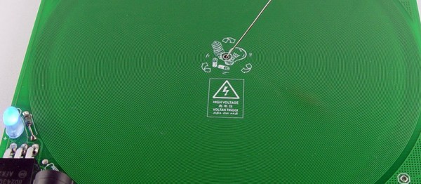
It looks a little strange, but this display works the same way a normal multiplexed display does but with the added benefit that each trace flows from one side to the other without turning back on itself at any point. To light any LED set the right row/column pair as source/sink and it turns on!
What if you actually need a rectangular display? Well that’s no problem, the matrix can be bent and smooshed as desired to change its shape. At the most extreme the possible display topologies get pretty wild! We’re sure to try thinking laterally next time we need to design an unusual display, maybe there is a more efficient matrix to be found.
![]()
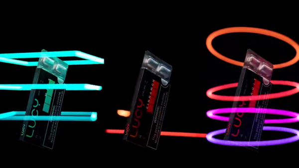
 Light painting is the process of moving a light while taking a long-exposure photograph, which creates a sort of drawing from the path of the light source. It’s been done in one way or another since at least the early-to-mid 1900s, but modern hardware and methods have allowed for all kinds of new spins on this old idea. [Josh Sheldon]