New parents will tell you that a baby takes a few months to acquire something close to a day/night sleep pattern, and during that time Mom and Dad also find their sleep becomes a a rarely-snatched luxury. [Seung Lee] has turned this experience into a unique data visualisation, by taking the sleep pattern data of his son’s first year of life and knitting it into a blanket.
The data was recorded using the Baby Connect app, from which it was exported and converted to JSON. This was in turn fed to some HTML/Javascript which generated a knitting pattern in a handy format that could be displayed on any mobile or portable device for knitting on the go. The blanket was then knitted by hand as a series of panels that were later joined into one, providing relief as the rows lined up.
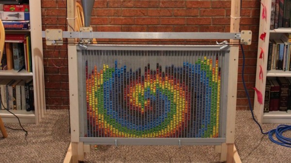
The finished product shows very well the progression as the youngster adapts to a regular sleep pattern, and even shows a shift to the right at the very bottom as a result of a trip across time zones to see relatives. It’s both a good visualisation and a unique keepsake that the baby will treasure one day as an adult. (Snarky Ed Note: Or bring along to the therapist as evidence.)
This blanket was hand-knitted, but it’s not the first knitted project we’ve seen. How about a map of the Universe created on a hacked knitting machine?