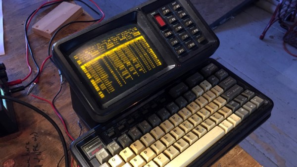
Vintage Logan Lathe Gets 3D Printed Gears

In December 2016, [Bruno M.] was lucky enough to score a 70+ year old Logan 825 lathe for free from Craigslist. But as you might expect for a piece of machinery older than 95% of the people reading this page, it wasn’t in the best of condition. He’s made plenty of progress so far, and recently started tackling some broken gears in the machine’s transmission. There’s only one problem: the broken gears have a retail price of about $80 USD each. Ouch.

On his blog, [Bruno] documents his attempts at replacing these expensive gears with 3D printed versions, which so far looks very promising. He notes that usually 3D printed gears wouldn’t survive in this sort of application, but the gears in question are actually in a relatively low-stress portion of the transmission. He does mention that he’s still considering repairing the broken gears by filling the gaps left by the missing teeth and filing new ones in, but the 3D printed gears should at least buy him some time.

As it turns out, there’s a plugin available for Fusion 360 that helpfully does all the work of creating gears for you. You just need to enter in basic details like the number of teeth, diametral pitch, pressure angle, thickness, etc. He loaded up the generated STL in Cura, and ran off a test gear on his delta printer.

Of course, it didn’t work. Desktop 3D printing is still a finicky endeavour, and [Bruno] found with a pair of digital calipers that the printed gear was about 10% larger than the desired dimensions. It would have been interesting to find out if the issue was something in the printer (such as over-extrusion) or in the Fusion 360 plugin. In any event, a quick tweak to the slicer scale factor was all it took to get a workable gear printed on the third try.

This isn’t the first time we’ve seen 3D printed gears stand in for more suitable replacement parts, nor the first time we’ve seen them in situations that would appear beyond their capability. As 3D printer hardware and software improves, it seems fewer and fewer of the old caveats apply.

Continue reading “Vintage Logan Lathe Gets 3D Printed Gears”

Home Decorating With Tiny Arcade Cabinets

Thanks to the general miniaturization of electronics, the wide availability of cheap color LCD screens, and the fact that licensing decades old arcade games is something of a free-for-all, we can now purchase miniature clones of classic arcade cabinets for about $20 USD. In theory you could play these things, but given they’re less than 4 inches in height they end up being more of a desk novelty than anything. Especially since it seems like most of the effort went into making the cabinet itself; a classic example of “form over function”.

Unfortunately, if you want to buy these little arcade cabinets to use as decoration for your office or game room, they aren’t particularly well suited to the task. The “demo” mode where the game plays itself doesn’t last for very long, and even if it did, the game would chew through batteries at an alarming rate. [Travis] decided to tackle both issues head on by powering his Tiny Arcades over USB and locking them into demo mode.

The stock power for the Tiny Arcade comes from three AAA batteries, or 4.5 V. This made it easy enough to run over  5 V USB, and a four port USB charger is used to provide power to multiple machines at once. Forcing the game to stay in demo mode wasn’t much harder: a 555 timer was used to “push” the demo button with a frequency of every 10 seconds or so to keep the game up and running. A simple timer circuit was put together in the classic “dead bug” style, and sealed up with liquid rubber so it would play nice with the insides of the Tiny Arcade.

Since his little machines wouldn’t need their stock power switches anymore, [Travis] rewired the speaker lead through it. So now the machine stays on and in demo mode as long as it’s plugged into USB power, and you can flip the switch on the back to turn off the sounds. Perfect for sitting up on a shelf or the corner of your desk.

Usability issues not withstanding, there’s a pretty big (no pun intended) following for micro sized arcade cabinets. We’ve seen projects ranging from modding a Game Boy Advance to even tinier scratch builds.

Continue reading “Home Decorating With Tiny Arcade Cabinets”

Debouncing The Old-Fashioned Way

If you were given the task of designing a computer at a time when computers weren’t really even a thing, how would you start? How would you take a collection of vacuum tubes, passive components, and a precious few germanium diodes and engineer something to sell to customers looking for an “electronic brain”?

Where there’s a paycheck, there’s a way, and computer archeologist [Ken Shirriff] laid his hands on some old IBM hardware that tells us a lot about how engineers thought in the earliest days of the computer industry. The gear is a pluggable module from IBM, one of hundreds that once went into their Model 705 computer from the mid-1950s. The particular module [Ken] has is a 5-channel contact debouncer, or in Big Blue’s mid-century parlance, a “Contact-Operated Trigger.” It was used to debounce five of the many, many mechanical contacts in the machine, both buttons and relays, and used eight dual triode tubes to do it. Other modules with the exact same footprint formed the flip-flops, inverters, buffers and clocks needed to build a computer.

[Ken]’s analysis of the debouncer is a fascinating look at what was possible with the technology of the day, and the fact that it led to a standardized framework for generic modules that were actually hot-swappable with what essentially was a zero insertion force plug was quite a feat of engineering. And as a bonus, [Ken] and friends actually got the module up in running in the video after the break.

Jonesing for more retro-computer pluggable goodness? Check out this reproduction IBM flip-flop module from the 1940s.

Continue reading “Debouncing The Old-Fashioned Way”

Bring Up A PCB With Fewer Headaches

What’s the first thing you do when a new set of boards from the fab house hits the doorstep? Apply solder paste, populate the components, and stick it in the reflow oven? That’s one way to do it. But a lot of non-obvious things can go wrong at the fab house, like shorts and undrilled vias. One tiny mistake can mean hours of frustration and sanity questioning as you troubleshoot some problem that’s now buried under solder paste and 0603s.

Over on IO, [Bhavesh] tries to nip these problems in the bud with a comprehensive and explanatory guide to properly bringing up a PCB. Though it’s based on fab house boards, this soup-to-nuts plan is good for any project from kit building to custom stripboard circuits. When new boards arrive, [Bhavesh] does several continuity checks and visually inspects them with a microscope. In the case of a stripboard layout, it’s a good idea to verify there’s no continuity across cut traces. He goes on to cover solder paste, touching on proper handling and storage, application, and problem correction.

Our favorite part of this guide is the component sheets. Making these is a great preventive measure, like lining up all your ingredients on the counter before you bake a cake. If you know what you need, why not have it all ready?  [Bhavesh] uses a sheet for each component type, lists all the relevant values in ascending order, and lays out component reels next to them.

The guide covers solder paste, too—his stencils were late to arrive, so the guide deals with applying paste by hand. He suggests a plan for populating the board by starting in one corner and working in circle, placing small components first. Then it’s on to reflow and those all-important post-reflow checks for bridges and bad joints before letting the magic smoke out.

A great time to catch mistakes is before you send the order to the fab house. Hackaday’s own [Joshua Vasquez] has you more than covered there.

34C3: Vintage Verification, Stop Nuclear War With A 6502

Our better-traveled colleagues having provided ample coverage of the 34C3 event in Leipzig just after Christmas, it is left to the rest of us to pick over the carcass as though it was the last remnant of a once-magnificent Christmas turkey.  There are plenty of talks to sit and watch online, and of course the odd gem that passed the others by.

It probably doesn’t get much worse than nuclear conflagration, when it comes to risks facing the planet. Countries nervously peering at each other, each jealously guarding their stocks of warheads. It seems an unlikely place to find a 34C3 talk about 6502 microprocessors, but that’s what [Moritz Kütt] and [Alex Glaser] managed to deliver.

Policing any peace treaty is a tricky business, and one involving nuclear disarmament is especially so. There is a problem of trust, with so much at stake no party is anxious to reveal all but the most basic information about their arsenals and neither do they trust verification instruments manufactured by a state agency from another player. Thus the instruments used by the inspectors are unable to harvest too much information on what they are inspecting and can only store something analogous to a hash of the data they do acquire, and they must be of a design open enough to be verified. This last point becomes especially difficult when the hardware in question is a modern high-performance microprocessor board, an object of such complexity could easily have been compromised by a nuclear player attempting to game the system.

We are taken through the design of a nuclear weapon verification instrument in detail, with some examples and the design problems they highlight. Something as innocuous as an ATtiny microcontroller seeing to the timing of an analogue board takes on a sinister possibility, as it becomes evident that with compromised code it could store unauthorised information or try to fool the inspectors. They show us their first model of detector using a Red Pitaya FPGA board, but make the point that this has a level of complexity that makes it unverifiable.

The gamma ray energy spectrum of a cobalt-60 source as seen from an Apple II.

Then comes the radical idea, if the technology used in this field is too complex for its integrity to be verified, what technology exists at a level that can be verified? Their answer brings us to the 6502, a processor in continuous production for over 40 years and whose internal structures are so well understood as to be de facto in the public domain. In particular they settle upon the Apple II home computer as a 6502 platform, because of its ready availability and the expandability of [Steve Wozniak]’s original design. All parties can both source and inspect the instruments involved.

If you’ve never examined a nuclear warhead verification device, the details of the system are fascinating. We’re shown the scintillation detector for measuring the energies present in the incident radiation, and the custom Apple II ADC board which uses only op-amps, an Analog Devices flash ADC chip, and easily verifiable 74-series logic. It’s not intentional but pleasing from a retro computing perspective that everything except perhaps the blue LED indicator could well have been bought for an Apple II peripheral back in the 1980s. They then wrap up the talk with an examination of ways a genuine 6502 system could be made verifiable through non-destructive means.

It is not likely that nuclear inspectors will turn up to the silos with an Apple II in hand, but this does show a solution to some of the problems facing them in their work and might provide pointers towards future instruments. You can read more about their work on their web site.

Tube Amps Are Still Tubular In 2018

Our friend [Pete] was reminiscing over the golden days with his old and broken antique Grundig Majestic console when he realized it deserved proper refurbishing. Now, any generic stereo record player might not be worth the time and effort to fix, but this was not any generic stereo record player. [Pete’s] inherited Grundig Majestic was his childhood favorite due to the distinct sound it had from the tubes that were used as the active elements. So he set out to fix both tube amps inside of the system.

[Pete] has had some experience working with audio equipment in the past. He did what we all aspire to, and got paid for doing what he loves by creating tube amps as a side gig. When he had finally had enough of the sub-par quality of bluetooth speakers that we all put up with for convenience sake, he decided to finally fix his favorite radio that had been lying around for far too long. He got to work immediately in his notebook finding what parts would be necessary for the reboot. The build ended up consisting of a HT supply regulated at 350V, an LT supply half DC-regulated at 6.3V, a 12AX7 input/bass/treble section, 6922 concertina tubes, and an EL34 ultra-linear output section. The end results yielded one amp that sounded just like it did in his youth, and one that isn’t quite there yet.

The Grundig Majestic is not done with just yet though. [Pete] plans to add a couple of additional modifications to his beauty when he’s not too busy with the kids. Firstly, perfecting the second amp is a top priority. After that, installing red LEDs that illuminate underneath the tubes would indicate low voltage presence, whereas blue illumination would indicate HT was locked and loaded. Bias monitoring to keep him informed on the status of the circuit conditions would insure smooth sailing down the road. Adding a relay connection of the speakers to the output transformer would minimize a popping sound that is currently being made in the speakers when the HT is initially turned on. These small improvements are just that — small — but that is part of what makes home projects so rewarding. The more you use something at home, the more you realize what needs to be refined further, so you are constantly learning more. It is a gratifying experience that I hope all of our readers have the chance to come across.

Tube amps are no stranger to Hackaday. Some of us have even built a few ourselves.

Thanks [Sophi]

Via Sparkfun

Go Retro To Build A Spectre And Meltdown-Proof X86 Desktop

[Yeo Kheng Meng] had a question: what is the oldest x86 processor that is still supported by a modern Linux kernel? Furthermore, is it actually possible to use modern software with this processor? It’s a question that surely involves experimentation, staring into the bluescreen abyss of BIOS configurations, and compiling your own kernel. Considering Linux dropped support for the 386 in 2012, the obvious answer is a 486. This supposition was tested, and the results are fantastic. You can, indeed, install a modern Linux on an ancient desktop.

This project got its start last month at a Super Silly Hackathon where [Yeo] and [Hui Jing] installed Damn Small Linux on an ancient IBM PS/1 desktop of 1993 vintage. The hardware consists of an AMD 486 clone running at 133MHz, 64 MB of RAM, a 48x IDE CDROM drive (wow!), a floppy emulator, a Sound Blaster, 10Mbps Ethernet card, and a CompactFlash to IDE adapter. By any account, this is a pimped-out rig for 1993 that would have cost more than a car at the time. The hardware works, but can you run a modern Linux kernel on it?

[Yeo] decided to install the Gentoo x86 minimal installation, but sanity and time constraints meant compiling a kernel on a 486 wasn’t happening. That was done on a modern Thinkpad after partitioning all the drives, verifying all the compilation parameters, and configuring the kernel itself. The bootloader is LILO (Grub2 didn’t work), but for the most part, this is entirely modern software running on a 25-year-old machine. The step-by-step instructions for becoming a /g/entooman on a 486 are available on GitHub.

The entire (boring) boot process can be seen in the video below. One interesting application of this build is that the 486 does not support out-of-order execution, making this completely safe from Meltdown and Spectre attacks. It’s an impressive retrocomputing achievement that right now could not be more timely.

Continue reading “Go Retro To Build A Spectre And Meltdown-Proof X86 Desktop”