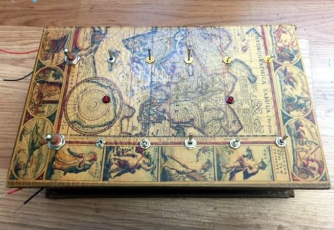
We all have too much stock of one component or another. Maybe you have more audio pots than you know what to do with, or maybe it’s zener diodes. For [technologyguy], that thing is a pile of toggle switches. Fortunately he’s always wanted to build a locking box with a binary code that’s laid out in switches — as in, find the right code, and a solenoid unlatches the box. This lovely parts bin special only responds 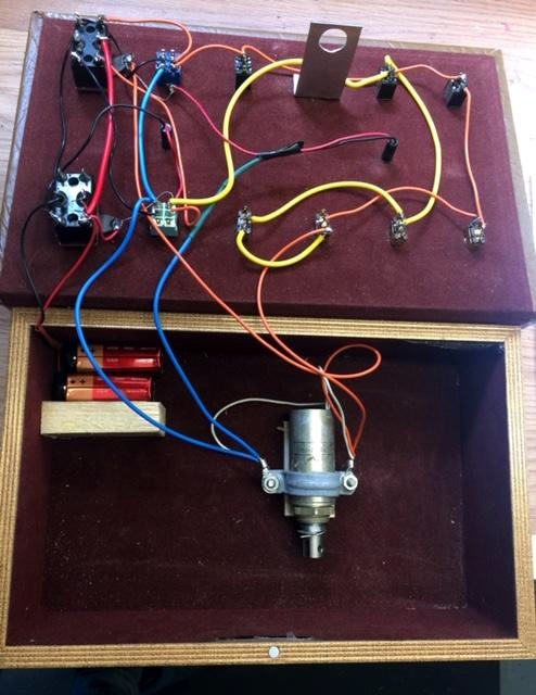 to two combinations out of a possible 4,000+, so anyone who tries to open it should probably block out the afternoon.
Inside you’ll find two 9 V batteries, a home-brew metal latch, a solenoid, and the undersides of four DPDT and eight SPDT toggle switches. If you just picked this thing up and had no idea what was going on, you’d be so screwed as to what to do first. The box needs power, so you’d have to figure out which switch is which. But it’s so much harder than that, because the bottom left switch selects between the two paths that result in an unlocked book-box.
The next two toggles in from the left are on/off selectors for code A and code B, so not only do you have to have the right path chosen, you have to power it, too. The only progress indicators are the LEDs — there’s one for main power, and the other lets you know that the box is unlatched. What a fun conversation piece for the coffee table Zoom-viewable area!
Want to do something far less useful with your throng of toggles? How about a complicated useless machine?