These magical creatures crop up out of nowhere and fry your electronics or annoy your ear holes. Understanding them will doubtless save you money and hassle. The ground loop in a nutshell is what happens when two separate devices (A and B) are connected to ground separately, and then also connected to each other through some kind of communication cable with a ground, creating a loop. This provides two separate paths to ground (B can go through its own connection to ground or it can go through the ground of the cable to A and then to A’s ground), and means that current may start flowing in unanticipated ways. This is particularly noticeable in analog AV setups, where the result is audio hum or visible bars in a picture, but is also sometimes the cause of unexplained equipment failures. Continue reading “WTF Are Ground Loops?”→
There comes a time in every electronic designer’s life when, whether they know it or not, they need an analog filter in their design. If you’re coming from a digital background, where everything is nice and numeric, the harsh reality of continuous voltages can be a bit of a shock. But if you’re taking input from, or sending output to the big analog world out there, it pays to at least think about the frequency-domain properties of the signal, and maybe even do something about them.
Designing an analog filter to fit your needs can be a bit of a daunting task: there are many factors that you’re going to need to consider, and they all interact. It’s easy to get lost. We’re going to simplify this as much as possible by instead focusing on a few common applications and building up the simplest possible filters that work well for them.
Today, we’re going to consider the lowpass filter, and specifically a Sallen-Key filter with Butterworth characteristics and a second-order rolloff. Sound like word salad? We’ll fix that up right away, because this is probably the single most important filter to have in your analog toolbox for two very common use cases: pulse-width modulated (PWM) output and analog-to-digital conversion (ADC) input.
In my misspent youth I found myself doing clinical rotations at a local hospital. My fellow students and I were the lowest of the low on the hospital pecking order, being the ones doing the bulk of the work in the department and paying for the privilege to do so. As such, our locker facilities were somewhat subpar: a corner of a closet behind a door labeled “COMMS”.
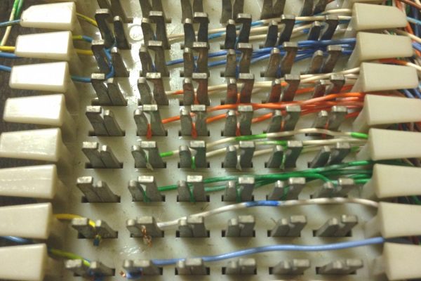
In the room was a broken chair and a couple of hooks on the wall for our coats, along with an intriguing (to me) electrical panel. It had a series of rectangular blocks with pins projecting from it. Each block had a thick cable with many pairs of thin, colorful wires fanned out and neatly connected to the left side, and a rats nest of blue and white wires along the right side. We were told not to touch the board. I touched it nonetheless.
I would later learn that these were Type 66 punchdown blocks for the department’s phone system, and I’d end up using quite a few of them over my hacking life. Punchdown connectors were a staple of both private and public telco physical plants for decades, and belong to a class of electrical connections called insulation displacement connections, or IDC. We’ve recently looked at how crimp connections work, and what exactly is going on inside a solder joint. I thought it might be nice to round things out with a little bit about the workings of IDC.
If you’ve hung around electronics for any length of time, you’ve surely heard of the decibel (often abbreviated dB). The decibel is a measure of a power ratio. Actually, the real measure is a bel, but you almost never see that in practice. If you are versed in metric, you won’t be surprised to learn a decibel is 1/10 of a bel. Sometimes in electronics, we deal with really large ratios, so the decibel is logarithmic to cope with this. Doubling the number of decibels doesn’t double the ratio, as you will soon see. It’s all about logarithms, and this ends up being extremely useful when measuring something like antenna or amplifier gain.
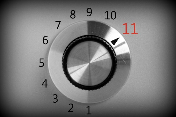
Besides antennas, decibels are often used to measure sound and light. The reason is that human ears and eyes have a logarithmic response to those quantities. Your ear, for example, has a huge dynamic range. That is to say, you can hear a whisper or a space shuttle launch. That ratio is about 1 trillion to 1, but that’s only 120 dB. This is also why potentiometers made for volume controls have a logarithmic taper. A linear pot would seem off because, for example, a tenth of a turn at one extreme will affect the apparent volume much more than a tenth of a turn at the other extreme. This holds true whether or not those knobs go up to eleven.
The Wimshurst machine is one of the oldest and best known electrostatic machines, consisting of its iconic two counter rotating disks and two Leyden jars. Most often you see someone hand cranking it, producing sparks, though we’ve seen it used for much more, including for powering a smoke precipitator for cleaning up smoke and even for powering a laser.
It works through an interesting sequence of events. Most explanations attempt to cram it all into one picture, requiring some major mental gymnastics to visualize. This often means people give up, resigned to assume these work through some mythical mechanics that defy a mortal’s ability to understand.
There is an old saying: “In theory, theory and practice are the same. In practice, they are not.” We spend our time drawing on paper or a computer screen, perfect wires, ideal resistors, and flawless waveforms. Alas, the real world is not so kind. Components have all kinds of nasty parasitic effects and no signal looks like it does in the pages of a text book.
Consider the following problem. You have a sine wave input coming in that varies between 0 V and 5 V. You want to convert it to a square wave that is high when the sine wave is over 2.5 V. Simple, right? You could use a CMOS logic gate or a comparator. In theory…
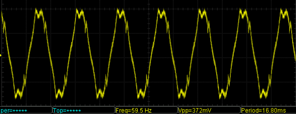
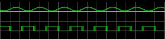
The problem is, the sine wave isn’t perfect. And the other components will have little issues. If you’ve ever tried this in real life, you’ll find that when the sine wave is right at the 2.5 V mark the output will probably swing back and forth before it settles down. This is exacerbated by any noise or stretching in the sine wave. You will wind up with something like this:
Notice how the edges of the square wave are a bit fat? That’s the output switching rapidly back and forth right at the comparator’s threshold.
Hysteresis
The answer is to not set the threshold at 2.5 V, or any other single value. Instead, impose a range outside of which it will switch, switching low when it leaves the low end of the range, and high when it exceeds the high end. That is, you want to introduce hysteresis. For example, if the 0 to 1 shift occurs at, say, 1.9 V and the 1 to 0 switch is at 0.5 V, you’ll get a clean signal because once a 0 to 1 transition happens at 1.9 V, it’ll take a lot of noise to flip it all the way back below 0.5 V.
You see the same effect in temperature controllers, for example. If you have a heater and a thermal probe, you can’t easily set a 100 degree set point by turning the heater off right away when you reach 100 and then back on again at 99.9999. You will usually use hysteresis in this case, too (if not something more sophisticated like a PID). You might turn the heater off at 99 degrees and back on again at 95 degrees, for example. Indeed, your thermostat at home is a prime example of a system with hysteresis — it has a dead-band of a few degrees so that it’s not constantly turning itself on and off.
Schmitt Triggers and How to Get One
A Schmitt Trigger is basically a comparator with hysteresis. Instead of comparing the incoming voltage with VCC / 2, as a simple comparator would, it incorporates a dead band to ensure that logic-level transitions occur only once even in the presence of a noisy input signal.
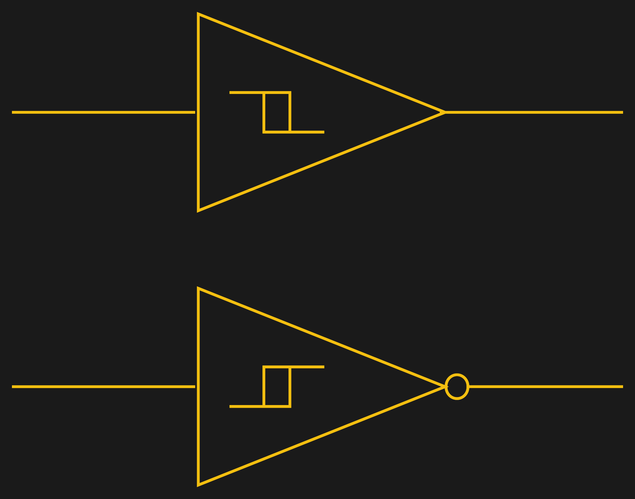
Assuming you want a Schmitt trigger in a circuit, you have plenty of options. There are ICs like the 74HC14 that include six (inverting) Schmitt triggers. On a schematic, each gate is represented by one of the symbols to the right; the little mark in the box is the hysteresis curve, and the little bubble on the output indicates logical negation when it’s an inverter.
You can also make them yourself out of transistors or even a 555 chip. But the easiest way by far is to introduce some feedback into a plain op amp comparator circuit.
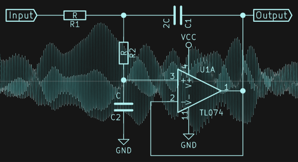
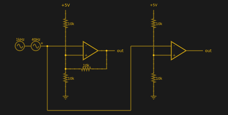
Below are two op amps, one with some positive feedback to make it act like a Schmitt trigger. The other is just a plain comparator. You can simulate the design online.
If you haven’t analyzed many op amp circuits, this is a good one to try. First, imagine an op amp has the following characteristics:
The inputs are totally open.
The output will do whatever it takes to make the inputs voltages the same, up to the power supply rails.
Neither of these are totally true (theory vs. practice, again), but they are close enough.
The comparator on the right doesn’t load the inputs at all, because the input pins are open circuit, and the output swings to either 0 V or 5 V to try, unsuccessfully, to make the inputs match. It can’t change the inputs because there is no feedback, but it does make a fine comparator. The voltage divider on the + pin provides a reference voltage. Anything under that voltage will swing the output one way. Over the voltage will swing it the other way. If the voltages are exactly the same? That’s one reason you need hysteresis.
The comparator’s voltage divider sets the + pin to 1/2 the supply voltage (2.5 V). Look at the Schmitt trigger (on top). If the output goes between 0 V and 5 V, then the voltage divider winds up with either the top or bottom resistor in parallel with the 10K feedback resistor. That is, the feedback resistor will either be connected to 5 V or ground.
Of course, two 10K resistors in parallel will effectively be 5K. So the voltage divider will be either 5000/15000 (1/3) or 10000/15000 (2/3) depending on the state of the output. Given the 5 V input to the divider, the threshold will be 5/3 V (1.67 V) or 10/3 V (3.33 V). You can, of course, alter the thresholds by changing the resistor values appropriately.
Practical Applications
Schmitt triggers are used in many applications where a noisy signal requires squaring up. Noisy sensors, like an IR sensor for example, can benefit from a Schmitt trigger. In addition, the defined output for all voltage ranges makes it handy when you are trying to “read” a capacitor being charged and discharged. You can use that principle to make a Schmitt trigger into an oscillator or use it to debounce switches.
If you want to see a practical project that uses a 555-based Schmitt, check out this light sensor. The Schmitt trigger is just one tool used to fight the imprecision of the real world and real components. Indeed, they’re nearly essential any time you want to directly convert an analog signal into a one-bit, on-off digital representation.
Wireless power transfer exists right now, but it’s not as cool as Tesla’s Wardenclyffe tower and it’s not as stupid as an OSHA-unapproved ultrasonic power transfer system. Wireless power transfer today is a Qi charger for your phone. It’s low power – just a few amps — and very short range. This makes sense; after all, we’re dealing with the inverse square law here, and wireless power transfer isn’t very efficient.
Now, suddenly, we can transfer nearly two kilowatts wirelessly to electronic baubles scattered all over a room. It’s a project from Disney Research, it’s coming out of Columbia University, it’s just been published in PLOS one, and inexplicably it’s also an Indiegogo campaign. Somehow or another, the stars have aligned and 2017 is the year of wirelessly powering your laptop.
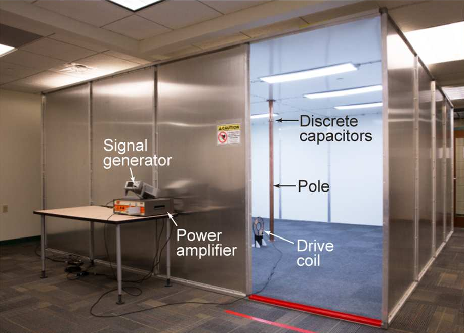
The first instance of wireless power transfer that’s more than just charging a phone comes from Disney Research. This paper describes quasistatic cavity resonance (QSCR) to transfer up to 1900 Watts to a coil across a room. In an experimental demonstration, this QSCR can power small receivers scattered around a 50 square meter room with efficiencies ranging from 40% to 95%. In short, the abstract for this paper promises a safe, efficient wireless power transfer that completely removes the need for wall outlets.
In practice, the QSCR from Disney Research takes the form of a copper pole situated in the center of a room with the walls, ceiling, and floor clad in aluminum. This copper pole isn’t continuous from floor to ceiling – it’s made of two segments, connected by capacitors. When enough RF energy is dumped into this pole, power can be extracted from a coil of wire. The video below does a good job of walking you through the setup.
As with all wireless power transmission schemes, there is the question of safety. Using finite element analysis, the Disney team found this room was safe, even for people with pacemakers and other implanted electronics. The team successfully installed lamps, fans, and a remote-controlled car in this room, all powered wirelessly with three coils oriented orthogonally to each other. The discussion goes on to mention this setup can be used to charge mobile phones, although we’re not sure if charging a phone in a Faraday cage makes sense.
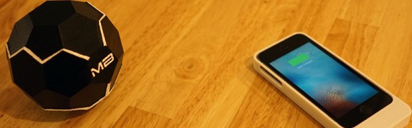
If the project from Disney research isn’t enough, here’s the MotherBox, a completely unrelated Indiegogo campaign that was launched this week. This isn’t just any crowdfunding campaign; this work comes straight out of Columbia University and has been certified by Arrow Electronics. This is, by all accounts, a legitimate thing.
The MotherBox crowdfunding campaign promises true wireless charging. They’re not going for a lot of power here – the campaign only promises enough to charge your phone – but it does it at a distance of up to twenty inches.
At the heart of the MotherBox is a set of three coils oriented perpendicular to each other. The argument, or sales pitch, says current wireless chargers only work because the magnetic fields are oriented to each other. The coil in the phone case is parallel to the coil in the charging mat, for instance. With three coils arranged perpendicular to each other, the MotherBox allows for ‘three-dimensional charging’.
Does the MotherBox work? Well, if you dump enough energy into a coil, something is going to happen. The data for the expected charging ranges versus power delivered is reasonably linear, although that doesn’t quite make sense in a three-dimensional universe.
Is it finally time to get rid of all those clumsy wall outlets? No, not quite yet. The system from Disney Research works, but you have to charge your phone in a Faraday cage. It would be a great environment to test autonomous quadcopters, though. For MotherBox, Ivy League engineers started a crowdfunding campaign instead of writing a paper or selling the idea to an established company. It may not be time to buy a phone case so you can charge your phone wirelessly at Starbucks, but at least people are working on the problem. This time around, some of the tech actually works.

 If the project from Disney research isn’t enough,


