Looking Mains Voltage In The Eye And Surviving

It is often a surprise to see how other people react to mains electricity when they encounter it in a piece of equipment. As engineers who have dealt with it both personally and professionally for many years it is easy to forget that not everyone has had that experience. On one hand we wince at those who dive in with no fear of the consequences, on the other we are constantly surprised at the number of people who treat any item with more than a few volts in it as though it was contaminated with radioactive anthrax and are scared to even think about opening it up.

We recently had a chat among the Hackaday writers about how we could approach this subject. The easy way out is to be all Elf-and-Safety and join the radioactive anthrax crowd. But the conclusion we came to was that this site is a resource for hackers and makers. Some of you are going to lift the lid on boxes containing significant voltages no matter what, so we thought we’d help you do it safely rather than just listen for the distant screams.

So here follows the first in a series on how to approach electronic devices containing high voltages, and live to tell the tale. By “high voltages” we mean anything up to mains voltages, and those directly derived from them such as the few hundred volts rectified DC you’ll find in a switch-mode PSU. For multi-kilovolt EHT you’ll have to wait for another article, because that is an entire subject in itself. We’ll mention these higher voltages in passing, but their detail is best left for a Hackaday colleague with more pertinent experience.

Continue reading “Looking Mains Voltage In The Eye And Surviving”

Overthinking Solenoid Control

No circuit is so trivial that it’s not worth thinking hard about. [Charles Wilkinson] wanted to drive a solenoid air valve that will stay open for long periods of time. This means reducing the holding current to prevent wasting so much power. He stumbled on this article that covers one approach in a ridiculous amount of depth.

[Charles] made two videos about it, one where he debugs the circuit and learns things live on camera, and another where he sums it all up. We’ll be walking you through the long one, but feel free to skip around.

Continue reading “Overthinking Solenoid Control”

How To Design, Manufacture, And Document A Hardware Product

It’s pretty awesome to have a hardware design hero jump at the chance to work on a Hackaday conference badge. I am of course talking about Voja Antonic.

I’ve gotten to know him over the last two years when we were introduced and he agreed to work on some original articles. He’s long been a hacker and shared his story of technology despite politics and society changing around him. His Galaksija computer was the first personal computer available in Yugoslavia with over 8,000 kits sold. Since those days he never stopped refining his design and fabrication skills. For instance, his method of making cases from FR4 is beyond compare, and reading some of his wisdom from hardware design in the casino industry is the kind of fascinating stuff that rarely makes it out for others to enjoy.

But I digress — the point is Voja’s been around the block, he knows what he’s doing, and he does it at an amazingly high level. He did an incredible job with the Hackaday | Belgrade conference badge. It features a 16×8 LED display, IR comms hardware, 5 user buttons, USB programming, an option for an accelerometer module, and has spectacular life running on two AAA batteries. It was a hit at the conference, and so was his talk discussing the design and fabrication. Check it out below and then join me below the fold.

Continue reading “How To Design, Manufacture, And Document A Hardware Product”

Megaprocessor Is A Macro Microprocessor

If we have to make a list of Projects that are insane and awesome at the same time, this would probably be among the top three right up there. For the past few years, [James Newman] has been busy building Megaprocessor – a huge micro-processor made out of transistors and LED’s, thousands of ’em. “I started by wanting to learn about transistors. Things got out of hand.” And quite appropriately, he’s based out of Cambridge – the “City of perspiring dreams“. The Why part is pretty simple – because he can. We posted about his build as recently as 10 months back, but he’s made a ton of progress since then and an update seemed in order.

megaprocessor_04How big is it ? For starters, the 8-bit adder module is about 300mm (a foot) long – and he’s using five of them. When fully complete, it will stretch 14m wide and stand 2m tall, filling a 30 sq.m room, consisting of seven individual frames that form the parts of the Megaprocessor.

The original plan was for nine frames but he’s managed to squeeze all parts in to seven, building three last year and adding the other four since then. Assembling the individual boards (gates), putting them together to form modules, then fitting it all on to the frames and putting in almost 10kms of cabling is a slow, painstaking job, but he’s been on fire last few months. He has managed to test and integrate the racks shown here and even run some code.

The Megaprocessor has a 16-bit architecture, seven registers, 256bytes of RAM and a questionable amount of PROM (depending on his soldering endurance, he says). It sips 500W, most of it going to light up all the LED’s. He guesses it weighs about half a ton. The processor uses up 15,300 transistors and 8,500 LED’s, while the RAM has 27,000 transistors and 2,048 LED’s. That puts it somewhere between the 8086 and the 68000 microprocessors in terms of number of transistors. He recently got around to calculating the money he’s spent on this to date, and it is notching up over 40,000 Quid (almost $60,000 USD)!  You can read a lot of other interesting statistics on the Cost and Materials page.

Continue reading “Megaprocessor Is A Macro Microprocessor”

Searching For USB Power Supplies That Won’t Explode

USB power supplies are super cheap and omnipresent. They are the Tribble of my household. But they’re not all created equal, and some of them may even be dangerous. I had to source USB power supplies for a product, and it wasn’t easy. But the upside is that I got to tear them all apart and check out their designs.

In order to be legitimate, it’s nice (but not legally required) for a power supply to have UL approval. Some retailers and offices and building managers require it, and some insurance companies may not pay claims if it turns out the damage was caused by a non-UL-approved device.  UL approval is not an easy process, though, and it is time consuming and expensive. The good news is that if you are developing a low voltage DC product, you can pair it with a UL approved power supply and you’re good to go without any further testing necessary.

power_supply_1_overviewIf you are going for FCC approval and are having unintentional emissions testing done (which is more likely than UL as it’s a legal requirement for products that meet certain qualifications), the testing has to be done on the whole solution, so the power supply must be included in the testing, too.

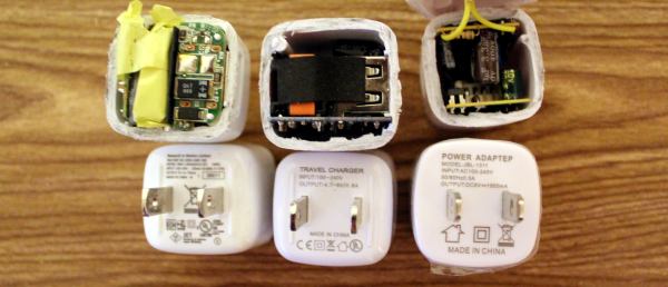
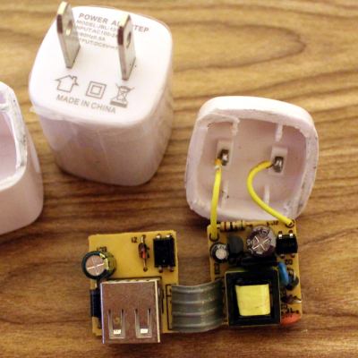
Sourcing cheap electronics in large quantities usually ends up in China, and specifically Alibaba. First, we started with a how-low-can-you-go solution. This wasn’t even a power adapter; it was a power “adapteP”, and the whole batch was mis-printed. Quality control could not be a high priority. After cutting it open, it wasn’t terrible, and it had all the necessary parts. It was surprising how much of it was through-hole, which indicates that the assembly was done mostly by people. That happens when factories are cheaper, hire inexpensive labor, don’t invest in technology, and don’t care as much about quality.

There are certain things you should look for in a power supply to determine the level of risk:

  • Isolation Distance – This is how much space there is between the primary (AC) and secondary (DC 5V) sides. UL requires a few millimeters, and often you’ll see two separate PCBs. On many single-PCB solutions you’ll see a white line meander across the board to distinguish between the two. The smaller this separation, the closer your USB power is to AC line voltage, and if the gap is bridged somehow, you’re in for a world of hurt.
  • Fuse – if there is a short, a lot of current starts flowing, components heat up, and things get dangerous. A thermal cut-off (TCO) fuse (also known as a resettable fuse or a PTC) is a component that breaks the circuit when it gets too hot, like a circuit chaperon. When it cools off, the TCO resets and you can plug the device back in with no harm done. Without the fuse, the supply heats up and current keeps flowing until a component fries, sometimes explosively.
  • Connectors – You don’t want bare leads hanging out in space where they could move and touch something. You don’t want the USB port to be soldered only by its four pins. You don’t want the power pins to be loose.
  • Decent Label – “Adaptep”? Yes, to someone who uses a different alphabet the “P” and R are very similar characters. But still. Also, fake certifications abound. Look for the difference between the CE (China Export) and the CE (Conformité Européenne) labels. And the UL Logo should have a number. So should an FCC label.

So this first adapter? Isolation distance was fine because it was two separate boards, but there was no fuse and no protective tape between components. The connectors were all secure, but the label didn’t make any promises. As for performance, output at 5.34V under my product’s load meant it was a little outside of USB spec (5.25V limit), but not dangerous. On the scope it was ringing with a peak at 5.5 V at 4 kHz.

Of course, sourcing this supply for a second batch proved tricky, and we wanted the USB plug to come out the side instead of the front so it would have a thinner profile against a wall. Additionally, we needed UL approval for a client. Our second attempt was surprisingly successful. This adapter had UL certification, with a number to look up. Note that just having a number isn’t enough; many companies will just put someone else’s number on their product and assume nobody will bother to check. So when you do look it up, and find a different manufacturer, a different enclosure, and it looks more like a refrigerator than a USB power supply, don’t be too surprised. But no, this particular one was great! The label had a company name on it, model number and specs, and certifications that could be verified. Let’s tear it open!

power_supply_2_overview
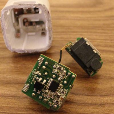
Sweet sweet silicon meat inside an ABS shell! Components wrapped in protective tape, two PCBs for isolation, and even a special injection-molded plastic piece to add additional protection. Components are labeled, and what’s this, an IC to control the oscillation instead of a feedback winding on the transformer? Fancy! It’s pretty clear that this power supply is good, and I’d trust this one.

Comparing this one to the others, there were so many noticeable little details that are important and clearly thought-out. Take, for example, the connection between the prongs and the PCB. On the previous board, it was made with wires soldered by hand. Solid, but time consuming and prone to failure or quality issues. This adapter has metal contacts that snap into the case very solidly so that the prongs cannot get loose. The connection to the PCB is via the springiness of the metal, but notice that the PCB has pads specifically designed to maximize the surface area of that connection. On the next PCB you’ll see no such effort.

Some components were covered in shrink tube, tape, or non-conductive grey adhesive. The assembly was tight with no room for components to shake loose or accidentally touch. And the output was perfect. 4.9 Volts with nary a ripple.

But this is China, and component sourcing problems are a thing, so I guess I shouldn’t have been surprised when these supplies were no longer available. In retrospect, maybe these were unsold overstock, or possibly QC rejects. That would explain why they were only slightly more expensive than the others. And so we moved on to another supplier; one that could pad-print our logo on top.

power_supply_differences
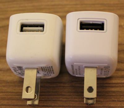
At first glance these power supplies appeared identical. But close inspection reveals slight differences in the style around the USB and the raised ridges on the underside. The label was completely different, and gone was the number next to the UL logo. There was no company name on the supply either, and the company we purchased from turned out to be a reseller and not the OEM. Also, why was the output 4.7-5V, and why did my scope say 5.5V (but surprisingly stable)?

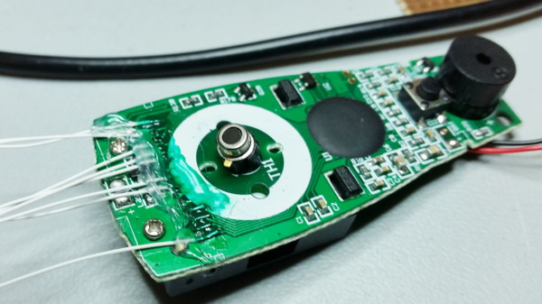
Inside was a completely different beast. Using a single PCB, the creep distance was about a millimeter. You can see the white line meandering through the bottom of the PCB that shows the high and low sides. The USB port wasn’t soldered to the PCB except by the four signal/power pins (see the bottom side lower left and the hanging USB connection pins), and there was a capacitor with really long uncovered leads and the positive side dangerously close to the USB shell. There was almost no protective tape, no shrink tube on the leads, and no protection in case of a short.


In the end, I wouldn’t trust the two non-UL supplies with anything worth more than a few bucks, and certainly not my cell phone. I’d have really big reservations about reselling them to customers who don’t know the difference. The UL-approved one was great, but the other two are only good for powering low-current-draw devices that are not sensitive to voltage. Also, finding a reliable supplier in China is HARD.

Check out a much more thorough analysis of this and pretty much every USB power supply cube by [Ken Shirriff]. It’s surprising how little has changed in four years with these supplies, and his analysis goes into how the circuits behind these supplies work, identifying each component and its purpose.

We also covered a Sparkfun teardown of some power supplies with similar conclusions, and a Fail of the Week in which a faulty USB power adapter was the likely cause of a fire.

Circuit Bender Artist Bends Fresnel Lens For Art

Give some mundane, old gear to an artist with a liking for technology, and he can turn it into a mesmerizing piece of art. [dmitry] created “red, an optic-sound electronic object” which uses simple light sources and optical elements to create an audio-visual performance installation. The project was the result of his collaboration with the Prometheus Special Design Bureau in Kazan, Russia. The inspiration for this project was Crystall, a reconstruction of an earlier project dating back to 1966. The idea behind “red” was to recreate the ideas and concepts from the 60’s ~ 80’s using modern solutions and materials.

The main part of the art installation consists of a ruby red crystal glass and a large piece of flexible Fresnel lens, positioned in front of a bright LED light source. The light source, the crystal and the Fresnel lens all move linearly, constantly changing the optical properties of the system. A pair of servos flexes and distorts the Fresnel lens while another one flips the crystal glass. A lot of recycled materials were used for the actuators – CD-ROM drive, an old scanner mechanism and old electric motors. Its got a Raspberry-Pi running Pure Data and Python scripts, with an Arduino connected to the sensors and actuators. The sensors define the position of various mechanical elements in relation to the range of their movement. There’s a couple of big speakers, which means there’s a beefy amplifier thrown in too. The sounds are correlated to the movement of the various elements, the intensity of the light and probably the color. There’s two mechanical paddle levers hanging in there, if you folks want to hazard some guesses on what they do.

Check out some of [dmitry]’s earlier works which we featured. Here’s him Spinning a Pyrite Record for Art, and making Art from Brainwaves, Antifreeze, and Ferrofluid.

Continue reading “Circuit Bender Artist Bends Fresnel Lens For Art”

Pillaging The Wealth Of Information In A Datasheet

It’s a fair assumption that the majority of Hackaday readers will be used to working with electronic components, they are the life blood of so many of the projects featured here. In a lot of cases those projects will feature very common components, those which have become commoditized through appearing across an enormous breadth of applications. We become familiar with those components through repeated use, and we build on that familiarity when we create our own circuits using them.

All manufacturers of electronic components will publish a datasheet for those components. A document containing all the pertinent information for a designer, including numerical parameters, graphs showing their characteristics, physical and thermal parameters, and some application information where needed. Back in the day they would be published as big thick books containing for example the sheets for all the components of a particular type from a manufacturer, but now they are available very conveniently online in PDF format from manufacturer or wholesaler websites.

A 2N3904 in a TO92 through-hole package

Datasheets are a mine of information on the components they describe, but sometimes they can be rather impenetrable. There is a lot of information to be presented, indeed when the device in question is a highly integrated component such as a DSP or microprocessor the datasheet can resemble a medium-sized book. We’re sure that a lot of our readers will be completely at home in the pages of a datasheet, but equally it’s a concern that a section of the Hackaday audience will not be so familiar with them and will not receive their full benefit. Thus we’re going to examine and explain a datasheet in detail, and hopefully shed some light on what it contains.

The device whose datasheet we’ve chosen to put under the microscope is a transistor. The most basic building block of active semiconductor circuits, and the particular one we’ve chosen is a ubiquitous NPN signal transistor, the 2N3904. It’s been around for a very long time, having been introduced by Motorola in the 1960s, and has become the go-to device for a myriad circuits. You can buy 2N3904s made by a variety of manufacturers all of whom publish their own data sheets, but for the purposes of this article we’ll be using the PDF 2N3904 data sheet from ON Semiconductor, the spun-off former Motorola semiconductor division. You might find it worth your while opening this document in another window  or printing it out for reference alongside the rest of this article.

Let’s take a look at all the knowledge enshrined in this datasheet, and the engineering eye you sometimes need to assign meaning to those numbers, diagrams, and formulas.

Continue reading “Pillaging The Wealth Of Information In A Datasheet”