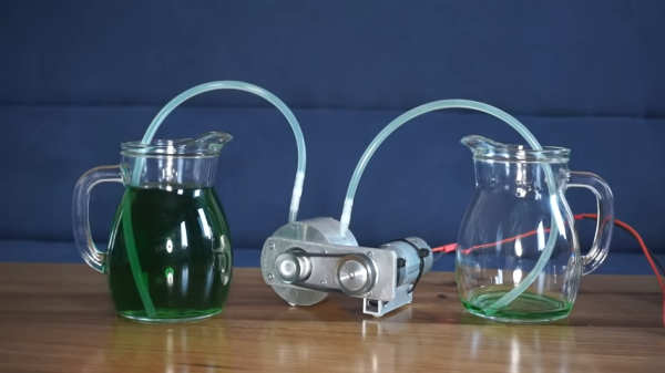
This Ruggedized Raspberry Pi Was Built To Be Copied

Over the last couple of years, we’ve seen a wave of impressive rugged mobile computing devices based on the ubiquitous Raspberry Pi. Sometimes they involve repurposing an existing heavy duty enclosure, and in others the Pi takes up residence in a 3D printed case which may or may not be as strong as it appears. In either event, they usually don’t lend themselves to duplication because of the time and expense involved in tracking down or printing all the parts required.

But the Raspberry Pi Quick Kit by [Jay Doscher] may change that. It represents what must surely be the simplest and fastest route to a building a rugged mobile ARM computer for your hacking adventures. Beyond the Pelican 1150 case that serves as the outer enclosure, you only need three printed parts and a handful of fasteners to complete the build. Of course you’ll need a Raspberry Pi and the official touch screen as well, but that’s sort of a given.

Electronics mounted to the 3D printed frame.

All of the electronics mount onto the three piece 3D printed frame, which is then press-fit into the opening of the Pelican case. Since you don’t need to pop any holes through the case itself, the assembled unit remains water and air tight. While [Jay] has recently shown off a very impressive 3D printed Pi enclosure, there’s really no beating a legitimate heavy duty storage case if you’re trying to protect the hardware.

When you want to use the Pi, just open the case and plug your power and accessories into the panel mount connectors under the display. There’s no integrated battery or keyboard on this build, but considering how small it is, that shouldn’t really come as a surprise.

[Jay] is targeting the Pi 4 for the Quick Kit, so that means WiFi and Bluetooth will come standard without the need for any external hardware. It looks like there might just be enough room to include an RTL-SDR receiver inside the case as well, but you’ll need to do a little redesigning of the 3D printed parts. If you do modify this design to pack in a few new tricks, we’d love to hear about it.

The Quick Kit is a greatly simplified version of the Raspberry Pi Recovery Kit that [Jay] unleashed on an unsuspecting world late last year. We’ve seen numerous variations on that original design sprout up since then, so we’re very interested to see what the response will be like to this much cheaper and easier to build version.

A Deep Dive Into The Sterzo Steering Plate

Pedaling in place isn’t the most exciting pastime, so it’s no surprise that modern technology is being used to make the in-home biking experience a bit more interactive. With a stand on the rear wheel providing resistance, and a movable steering plate under the front to read the handlebar angle, you can now use your standard bike as the “controller” in a virtual environment provided by software such as Zwift.

Paving the way towards a DIY Sterzo clone

[Keith Wakeham] wanted to take a closer look at how Zwift communicated with his Sterzo steering device, and it turned into a pretty epic bout of exploration and reverse engineering. As the video after the break shows, he didn’t just go from sniffing the device’s proprietary Bluetooth Low Energy (BLE) communications protocol to figuring out how to emulate it in software so you could roll your own Zwift peripheral. He also tore the device apart, pulled the firmware from its microcontroller, and postulated how you could build your own low-cost clone device that would work with the existing software.

Even if you have absolutely zero interest in virtual biking, the video [Keith] has put together for this project is really a must watch. Have you ever wanted to sniff and reverse engineer BLE communications? Looking for a real-world example of pulling the firmware off of a consumer device? Maybe in the market for some tips on how to identify unknown ICs on a board? All of that, and quite a bit more, is covered in this nearly hour long hacking tour de force.

On the other hand, if you are interested in adding your own hardware to Zwift, then this look at getting an unsupported stationary bike working with it should be useful.

Continue reading “A Deep Dive Into The Sterzo Steering Plate”

Wooden Tank’s Movement Hinges On Hinges

When we first looked at this tank, we thought it was pretty cool. The sides are unpainted 1/2″ (12mm) plywood, so it is not flashy. The dimensions came from Google-fu-ing the heck out of the WWII Hetzer and scaling them to 1:6. What knocks our socks off is how much [Bret Tallent] made use of parts you would find in a hardware store or bicycle shop. He uses twin motors from electric bikes, and the wheels look like replacement shopping cart wheels. The best part is the treads, which are dozens of hinges fastened with pairs of bolts and nylon-insert nuts. Something is reassuring about knowing that a repair to your baby is no further than a bike ride.

We don’t know what started [Bret] on his path to sidewalk superiority, but we suspect he is cooped up like the rest of us and looking to express himself. Mini-Hetzer is not licensed by Power Wheels and never will be, so it probably won’t turn into a business anytime soon. There is a complete gallery starting with an empty plywood base, and the pictures tell the story of how this yard Jäger got to this point. There are plans to add a paintball gun and streaming video, so we’d advise that you don’t mess with the jack-o-lanterns on his block this year. Give his gallery a view and see if you don’t become inspired to cobble something clever from the hardware store too. Then, tell us about it.

Another creative hacker used wood for their tank body and the treads as well. If you like your treaded vehicles functional, we have one meant to taxi small planes over the tarmac.

DIY Relay Module Saves Time

As any programmer could tell you, there’s significant value in automating a process that is performed often enough. The more times that process is used, the more it makes sense to automate it or at least improve its efficiency. This rule isn’t limited to software though; improvements to hardware design can also see improvements in efficiency as well. For that reason, [Hulk] designed a simple relay module in order to cut the amount of time he spends implementing this solution in his various other projects.

While driving a relay with a transistor is something fundamental, this project isn’t really about that per se. It’s about recognizing something that you do too much, and then designing that drudgery out of your projects. [Hulk] was able to design a PCB with 12 modules on it, presumably saving fabrication costs. He can then easily populate them with specific components as soon as he needs one. Another benefit of designing something like this yourself, rather than an off-the-shelf relay module, is that you can do away with any useless features you’ll never need (or add ones that aren’t available in commercial devices).

We can appreciate the efficiency gains this would make for our next project that needs a simple driver for a light, garage door opener, or any other binary electronic device. It can be a hassle to go find the correct transistor and relay, solder it all on the project board, and hope it all works. A pre-made solution solves all these issues, but we do wish the schematics were available to keep us from having to design our own. Driver boards are a pretty common project for all the different types of relays we see around here, so there is probably one available out there.

Perfect Photographs For PCB Reverse Engineering

There’s an unexpected part of hacking that is very difficult to get right, namely photographing printed circuit boards. Everything seems to catch the light, making for a complex dance of manipulating light sources and camera angles. We were thus captured by [Roman Valls]’ budget rig for taking PCB photos that makes ingenious use of roadside trash to achieve a result.

It was inspired by a video featuring a much more accomplished rig, which he set out to emulate for much less outlay. Instead of an expensive lens, he’s using a Nikon camera with its kit lens. And instead of a tripod there’a a scrap drawer salvaged from the roadside and modified to become a camera holder. Lighting is diffused by baking paper, and the result is a rig that can photograph PCBs with neutral lighting and without annoying highlights.

We especially like work that takes junk and makes something useful from it, and though our purpose isn’t in reverse engineering it’s impressive to see how well the technique reveals the traces. We’ll definitely be experimenting with some of the techniques herein, and those lighting tips might also work with the Hackaday ear camera microscope.

An Analog IC Design Book Draft

[Jean-Francois Debroux] spent 35 years designing analog ASICs. He’s started a book and while it isn’t finished — indeed he says it may never be — the 180 pages he posted on LinkedIn are a pretty good read.

The 46 sections are well organized, although some are placeholders. There are sections on design flow and the technical aspects of design. Examples range from a square root circuit to a sigma-delta modulator, although some of them are not complete yet. There are also sections on math, physics, common electronics, materials, and tools.

Continue reading “An Analog IC Design Book Draft”

Transparent OLED Hitting The Market With Xiaomi’s Mi TV LUX Transparent Edition

One of the major advantages of OLED over LCD panels is that the former can be made using far fewer layers as the pixels themselves are emitting the light instead of manipulating the light from a backlight. This led some to ask the question of whether it’s possible to make an OLED panel that is transparent or at least translucent. As Xiaomi’s new Mi TV LUX OLED Transparent Edition shows, the answer there is a resounding ‘yes’. Better yet, for a low-low price of about $7,200 you can own one of these 55″ marvels.

Transparent OLED technology is not new, of course. Back in 2018 LG was showing off a prototype TV that used one of the early transparent OLED panels. In the video that is embedded after the break, [Linus] from Linus Tech Tips goes hands-on with that LG prototype while at LG in South Korea, while including a number of crucial details from an interview from one of the engineers behind that panel.

As it turns out, merely removing the opaque backing from an OLED panel isn’t enough to make it transparent. In order for an OLED panel to become transparent, the circuitry in the pixel layer and TFT layer need to be aligned as best as possible to allow for many, many tiny holes to be punched through the display.

Looking at [Linus]’s experiences with the LG prototype, it does appear that this kind of technology would be highly suitable for signage purposes, while also allowing for something like an invisible television or display in a room that could be placed in front of a painting or other decoration. Once displaying an image, the screen is bright enough that you can comfortably make out the image. Just don’t put any bright lights behind the TV.

Anyone else anxious waiting for sub-10″ versions of these panels?

Continue reading “Transparent OLED Hitting The Market With Xiaomi’s Mi TV LUX Transparent Edition”