DIY Induction Soldering Iron

[Kasyan TV] shows us how to make a really simple DIY induction soldering iron complete with DIY soldering tips.

This is a pretty cool project. Most of us are used to temperature controlled ceramic heating elements, but there are other ways to get those irons up to temperature. Using scraps from older, presumably broken, soldering irons and some pieces of copper and iron along with a thermocouple for temperature management, [Kasyan TV] manages to throw together an Inductively heated soldering iron. To insulate the coil from the iron they use Kapton tape. The video goes on to show how to make your own induction iron, although missing is a power supply. We are sure a quick eBay search for an induction heater module should bring up something suitable to power the iron, or you could just wait and watch the their next video that will go over power supplies. The soldering tips are simply made from thick copper wire sculpted into the correct shape.

There are advantages to using a soldering iron like this, for example they are pretty durable and will take a knock or two, Our concern is that magnetically sensitive parts may not be happy, and the iron might destroy what you are trying to build. Either way we’ve put the video below the break, so take a look.

Hackaday has featured a few different DIY soldering irons and some pretty cool DIY Soldering Stations over the years. What is your soldering iron of choice and why?

Continue reading “DIY Induction Soldering Iron”

Practical Enclosure Design, Optimized For 3D Printing

[3D Hubs] have shared a handy guide on designing practical and 3D printing-friendly enclosures. The guide walks through the design of a two shell, two button remote control enclosure. It allows for a PCB mounted inside, exposes a USB port, and is optimized for 3D printing without painting itself into a corner in the process. [3D Hubs] uses Fusion 360 (free to hobbyists and startups) in their examples, but the design principles are easily implemented with any tool.

One of the tips is to design parts with wall thicknesses that are a multiple of the printer’s nozzle diameter. For example, a 2.4 mm wall thickness may sound a bit arbitrary at first, but it divides easily by the typical FDM nozzle diameter of 0.4 mm which makes slicing results more consistent and reliable. Most of us have at some point encountered a model where the slicer can’t quite decide how to handle a thin feature, delivering either a void between perimeters or an awkward attempt at infill, and this practice helps reduce that. Another tip is to minimize the number of sharp edges in the design, because rounded corners print more efficiently and with smoother motions from the print head.

The road to enclosures has many paths, including enclosures made from FR4 (aka PCB material) all the way down to scrap wood with toner transfer labeling, and certainly desktop 3D printing has been a boon to anyone who’s had to joylessly drill and saw away at a featureless plastic box.

Quick And Dirty Shock Gloves

[JLaservideo] has created some cool high-voltage gloves and uploaded a video on YouTube showing you how to get your mitts on a pair of your own. Using some very simple parts, he manages to make some decent sparks.

At the heart of this project is one of those new-fangled arc lighters which normally use some type of voltage multiplier circuit to function. The rest of the build is just wire, glue, aluminum foil, a switch, and paintball gloves.

Using the tip of each finger as an electrode, anything he touches will complete the circuit, creating high-voltage arcs. The demo of burning through paper is pretty neat, although we’ll admit we’re at a loss to think of what other tricks you could pull off with electrified fingertips. Anyone?

Continue reading “Quick And Dirty Shock Gloves”

The Science Behind Boost Converters

[Ludic Science] shows us the basic principles that lie behind the humble boost converter. We all take them for granted, especially when you can make your own boost converter or buy one for only a few dollars, but sometimes it’s good to get back to basics and understand exactly how things work.

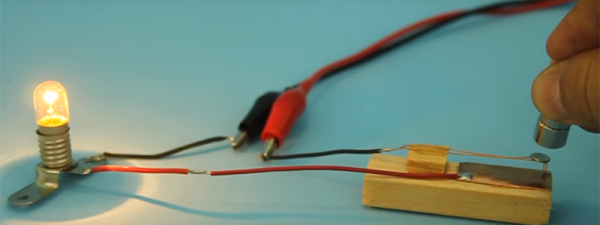
The circuit in question is probably as simple as it gets when it comes to a boost converter, and is not really a practical design. However it helps visualize what is going on, and exactly how a boost converter works, using just a few parts, a screw, enameled wire, diode, capacitor and a push button installed on a board.

The video goes on to show us the science behind a boost converter, starting with adding a battery from which the inductor stores a charge in the form of an electromagnetic field. When the button is released, the magnetic field collapses, and this causes a voltage in the circuit which is then fed through a diode and charges the capacitor a little bit. If you toggle the switch fast enough the capacitor will continue to charge, and its voltage will start to rise. This then creates a larger voltage on the output than the input voltage, depending on the value of the inductor. If you were to use this design in a real life application, of course you would use a transistor to do the switching rather than a push button, it’s so much faster and you won’t get a sore finger.

This is very basic stuff,  but the video gives us a great explanation of what is happening in the circuit and why. If you liked this article, we’re sure you’ll love Hackaday’s own [Jenny List] explain everything you need to know about inductors.

(updated thanks to [Unferium] – I made a mistake about the magnetic field collapsing when the button is pressed , When in reality it’s when the button is released that this happens. Apologies for confusion.)

Continue reading “The Science Behind Boost Converters”

Manual LCD Makes Information Display Tedious, Educational

The HD44780 is one of the first chips we learned about as a kid, and chances are good you’ve used one in your project at some point, and almost certain that you’ve interacted with one in your life. The character LCD is ubiquitous, easy to interface, and very robust. They come in sizes from 8 x 1 to 20 x 4 and even larger, but they almost all have the same pinout, and there are libraries in many embedded environments for interacting with them. [The 8-Bit Guy] decided to interface with one using just switches and a button, (YouTube, embedded) with the intent of illustrating exactly how to use them, and how easy they are.

Continue reading “Manual LCD Makes Information Display Tedious, Educational”

PogoPlug Hacking: A Step By Step Guide To Owning The Device

[Films By Kris Hardware] has started quite an interesting YouTube series on hacking and owning a PogoPlug Mobile v4. While this has been done many times in the past, he gives a great step by step tutorial. The series so far is quite impressive, going into great detail on how to gain root access to the device through serial a serial connection.

PogoPlugs are remote-access devices sporting ARM processor running at 800 MHz, which is supported by the Linux Kernel.  The version in question (PogoPlug Mobile v4) have been re-purposed in the past for things like an inexpensive PBX, an OpenWrt router and even a squeezebox replacement. Even if you don’t have a PogoPlug, this could be a great introduction to hacking any Linux-based consumer device.

So far, we’re at part three of what will be an eight-part series, so there’s going to be more to learn if you follow along. His videos have already covered how to connect via a serial port to the device, how to send commands, set the device up, and stop it calling home. This will enable the budding hacker to make the PogoPlug do their bidding. In this age of the cheap single-board Linux computer, hacking this type of device may be going out of style, but the skills you learn here probably won’t any time soon.

Continue reading “PogoPlug Hacking: A Step By Step Guide To Owning The Device”

Dual SIM Hack For Single SIM Slot Phones.

[RoyTecTips] shows us an ingenious hack which turns a single-SIM-slot phone into a fully functioning dual-SIM phone. All that’s needed for this hack is a heat-gun, solvent, micro SD card, nano SIM and some glue. The trick is that the phone has a SIM reader on the backside of an SD-card slot. Through some detailed dissection and reconstruction work, you can piggy-back the SIM on the SD card and have them both work at the same time.

Making the SD/SIM Franken-card is no picnic. First you start by filing away the raised bottom edge of the micro SD card and file down the side until the writing is no longer visible. Next get a heat gun and blast your nano SIM card until the plastic melts away. Then mark where the SIM card’s brains go and glue it on. Turn the phone on then, hey presto, you now have a dual SIM phone while keeping your SD storage.

This hack is reported to work on many Samsung phones that end in “7” and some that end in “5”, along with some 8-series phones from Huawei and Oppo clones of the Samsungs. Since you’re only modifying the SIM card, it’s a fairly low-risk hack for a phone. Combining two cards into one is certainly a neat trick, almost as neat as shoe-horning a microcontroller into an SD card. We wonder how long it will be before we see commercial dual SIM/SD cards on the market.

[Update] I got a little confused on this one as we only have the single sim variants of these phones where I live. this hack is for dual sim phones that either accept 2 sim cards or 1 sim + 1 SD card. This hack solves this problem and allows 2 sims plus 1 SD card in these phones. Sorry for the confusion and thanks to all who pointed this out in the comments.

Continue reading “Dual SIM Hack For Single SIM Slot Phones.”