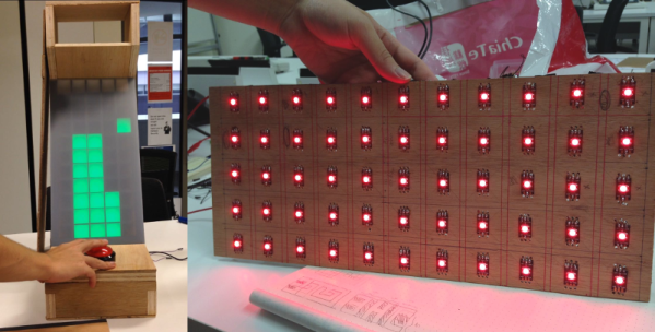
For [LumoW], what started as a school project turned into a passion project. He and his team made a hardware implementation of an arcade game called Stacker. Never heard of it? It’s pretty fun, kind of like an inverse Tetris. You can play the flash version here and see their mini arcade version after the break.
The game is based around the Mojo FPGA which the class required, and it’s programmed entirely in bitwise operators. It uses WS2812 RGB LEDs to represent the individual tower building blocks, and these are mounted on plywood in a matrix and separated into cells by a grid of foam board. After some trial and error, the team found the perfect shade of acrylic to diffuse the bright dots into glowing squares.
Since the game only needs one input, we don’t think [LumoW] should apologize at all for using the biggest, baddest button they could find. Besides, the game has that edge-of-your-seat action that can turn panic into heavy-handedness and cool DIY arcade games into shards of sadness.
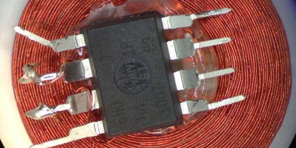
One of Atmel’s smallest microcontrollers, the ATtiny, is among the most inexpensive and reliable chips around for small applications. It’s also one of the most popular. If you don’t need more than a few inputs or outputs, there’s nothing better. As a show of its ability to thrive under adverse conditions, [Trammell Hudson] was able to shoehorn an ATtiny into an RFID circuit in a way that tests the limits of the chip design.
The RFID circuit only uses two of the ATtiny’s pins and neither of which is the ground or power pin. The ATtiny is equipped with protective diodes on its input pins, and if you apply an AC waveform to the input pins, the chip is able to use the leakage current to power itself. Once that little hurdle is crossed, the ATtiny can do the rest of its job handling the RFID circuitry.
This project takes a deep dive into the internals of the ATtiny. If you’ve ever wondered what was going on inside of everyone’s favorite tiny microcontroller, or if you’re looking for an RFID circuit that keeps parts counts to an absolute minimum, this is the project for you. The ATtiny is more than just a rugged, well-designed chip, though. It’s capable of a lot more than such a small chip should be able to.
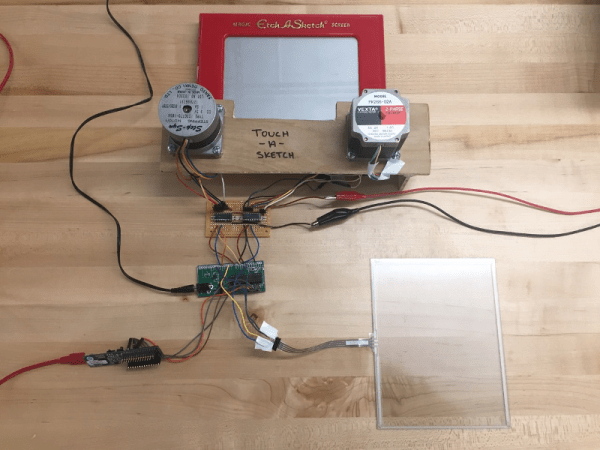
After nearly 60 years and a lot of stairs and squares, there is finally an easier way to draw on an Etch A Sketch®. For their final project in embedded microcontroller class, [Serena, Francis, and Alejandro] implemented a motor-driven solution that takes input from a touch screen.
Curves are a breeze to draw with a stylus instead of joysticks, but it’s still a 2-D plotter and must be treated as such. The Touch-A-Sketch system relies on the toy’s stylus starting in the lower left hand corner, so all masterpieces must begin at (0,0) on the knobs and the touch screen.
The BOM for this project is minimal. A PIC32 collects the input coordinates from the touch screen and sends them to a pair of stepper motors attached to the toy’s knobs. Each motor is driven by a Darlington array that quickly required a homemade heat sink, so there’s even a hack within the hack. The team was unable to source couplers that could deal with the discrepancy between the motor and knob shaft sizes, so they ended up mounting the motors in a small plywood table and attaching them to the stock knobs with Velcro. This worked out for the better, since the Etch A Sketch® screen still has to be reset the old-fashioned way.
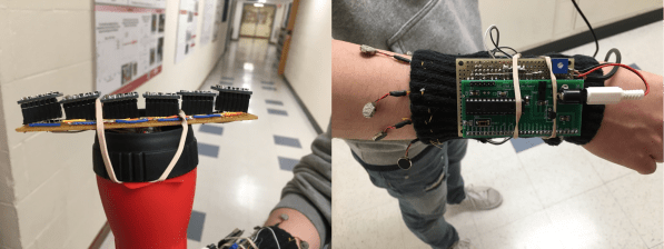
For their final project in embedded microcontroller class, [Aaheli, Jun, and Naomi] turned their focus toward assistive technology and created an Electronic Travel Aid (ETA) for the visually impaired that uses haptic feedback to report the presence of obstacles.
We have seen a few of these types of devices in the past, and they almost always use ultrasonic sensors to gauge distance. Not so with this ETA; it uses six VL53L0X time-of-flight (ToF) sensors mounted at slightly different angles from each other, which provides a wide sensing map. It is capable of detecting objects in a one-meter-wide swath at a range of one meter from the sensors.
The device consists of two parts, a wayfinding wand and a feedback module. The six ToF sensors are strapped across the end of a flashlight body and wired to an Arduino Mini inside the body. The Mini receives the sensor data over UART and sends it to the requisite PIC32, which is attached to a sleeve on the user’s forearm. The PIC decodes these UART signals into PWM and lights up six corresponding vibrating disc motors that dangle from the sleeve and form a sensory cuff bracelet around the upper forearm.
We like the use of ToF over ultrasonic for wayfinding. Whether ToF is faster or not, the footprint is much smaller, so its more practical for discreet assistive wearables. Plus, you know, lasers. You can see how well it works in the demo video after the break.
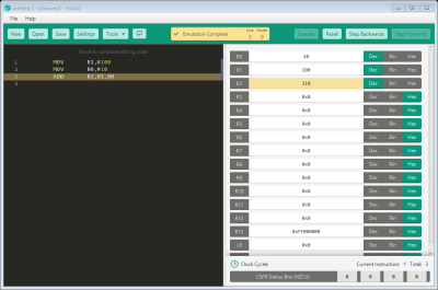
Learning assembly is very important if you want to get a grasp of how a computer truly works under the hood. VisUAL is a very capable ARM emulator for those interested in learning the ARM assembly.
The GUI: A simply program to ADD two numbers
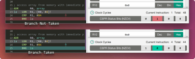
In addition to supporting a large subset of ARM instructions, the CPU is emulated via a series of elaborate and instructive animations that help visualise the flow of data to/from registers, any changes made to flags, and any branches taken. It also packs very useful animations to help grasp some of the more tricky instruction such as shifts and stack manipulations.
As it is was designed specifically to be used as teaching tool at Imperial College London, the GUI is very friendly, all the syntax errors are highlighted, and an example of the correct syntax is also shown.
You can also do the usual things you would expect from any emulator, such as single step through execution, set breakpoints, and view data in different bases. It even warns you of any possible infinite loops!
That being said, lugging such an extravagant GUI comes at a price; programs that consume a few hundred thousand cycles hog far too much RAM should be run in the supported headless mode.
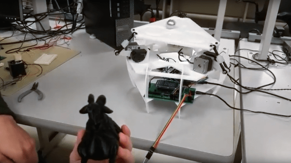
No goats were harmed in the making of this 3-DOF Stewart platform for [Bruce Land]’s microcontrollers course at Cornell.
If the name “Stewart platform” doesn’t ring a bell, the video below will help you out. [Team Microgoats] built a small version of the mechanical system commonly seen in flight simulators, opting for 3 DOF to simplify the design. Their PIC32-controlled steppers can wobble and weave the table in response to inputs from an MPU-6050 six-axis accelerometer embedded in the base of a 3D-printed goat. Said goat appears to serve no other role in the build, but goats are cool, so why not? And if you’ve ever seen a mountain goat frolicking across a sheer vertical rock face like it was walking across a parking lot, you’ll understand the connection to the balance and control offered by a Stewart platform.
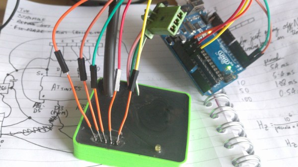
After swapping the engine out in his scooter, [James Stanley] made an unfortunate discovery. The speedometer was digitally controlled, and while the original engine had a sensor which would generate pulses for it to interpret, his new engine didn’t. Learning that the original sensor would pull the signal wire to ground each time it detected a tooth of one of the spinning gears, [James] reasoned he needed to find a way to detect the scooter’s speed and create these pulses manually.
To find the scooter’s speed, he installed a magnet on the front wheel and a hall effect sensor on the fork to detect each time it passed by. Since the wheel is of a known circumference, timing the pulses from the sensor allows calculation of the current speed. A GPS receiver could be used if you wanted fewer wires, but the hall effect sensor on the wheel is simple and reliable. With the speed of the scooter now known, he needed to turn that into a signal the speedometer understands.
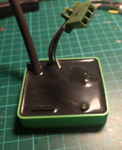
Speedometer controller potted with resin.
[James] wrote a program for an ATmega that would take the input from the wheel sensor and use it to create a PWM signal. This PWM signal drives a transistor, which alternates the speedometer sensor wire between low and floating. With a bit of experimentation, he was able to come up with an algorithm which equated wheel speed to the gearbox speed the speedometer wanted with accuracy close enough for his purposes.
While the software side of this project is interesting in its own right, the hardware is an excellent case study in producing robust electronic devices suitable for use on vehicles. [James] 3D printed a shallow case for the circuit board, and potted the entire device with black polyurethane resin. He even had the forethought to make sure he had a debugging LED and programming connector before he encapsulated everything (which ended up saving the project).
While the specific scenario encountered by [James] is unlikely to befall others, his project is an excellent example of not only interfacing with exiting electronics but producing rugged and professional looking hardware without breaking the bank. Even if scooters aren’t your thing, there are lessons to be learned from this write-up.