Microcontroller Load Meter Tells You How Hard It’s Currently Working

Writing code for embedded applications can be difficult. There are all sorts of problems you can run into – race conditions, conflicting peripherals, unexpected program flow – any of these can cause havoc with your project. One thing that can really mess things up is if your microcontroller is getting stuck on a routine – without the right debugging hardware and software, this can be a tricky one to spot. [Terry] developed a microcontroller load meter just for this purpose.

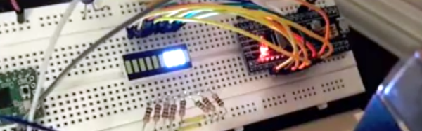
It’s a simple setup – a routine named loadmeter-task on the microcontroller sends a train of pulses to a mechanical ammeter. The ammeter is then adjusted with a trimpot to read “0” when the chip is unloaded. As other tasks steal CPU time, there’s less time for loadmeter-task to send its pulses, so the meter falls to the left.

Overall it’s a quick and easy bit of code you could add to any project with a spare GPIO pin, that might help you debug. Plus it’s cool to know how hard your project is pushing the silicon.

If you’d like to know more about what your chip is doing, check out this post about the usefulness of in-circuit debugging, or read about Bil Herd’s experiments with ICE and OBD-II.

OBDII to Speed Pulse: Atmel ICE

Building An OBD Speed Pulse: Behold The ICE

I am a crappy software coder when it comes down to it. I didn’t pay attention when everything went object oriented and my roots were always assembly language and Real Time Operating Systems (RTOS) anyways.

So it only natural that I would reach for a true In-Circuit-Emulator (ICE) to finish of my little OBDII bus to speed pulse generator widget. ICE is a hardware device used to debug embedded systems. It communicates with the microcontroller on your board, allowing you to view what is going on by pausing execution and inspecting or changing values in the hardware registers. If you want to be great at embedded development you need to be great at using in-circuit emulation.

Not only do I get to watch my mistakes in near real time, I get to make a video about it.

Getting Data Out of a Vehicle

I’ve been working on a small board which will plug into my car and give direct access to speed reported on the Controller Area Network (CAN bus).

To back up a bit, my last video post was about my inane desire to make a small assembly that could plug into the OBDII port on my truck and create a series of pulses representing the speed of the vehicle for my GPS to function much more accurately. While there was a wire buried deep in the multiple bundles of wires connected to the vehicle’s Engine Control Module, I have decided for numerous reasons to create my own signal source.

At the heart of my project is the need to convert the OBDII port and the underlying CAN protocol to a simple variable representing the speed, and to then covert that value to a pulse stream where the frequency varied based on speed. The OBDII/CAN Protocol is handled by the STN1110 chip and converted to ASCII, and I am using an ATmega328 like found on a multitude of Arduino’ish boards for the ASCII to pulse conversion. I’m using hardware interrupts to control the signal output for rock-solid, jitter-free timing.

Walk through the process of using an In-Circuit Emulator in the video below, and join me after the break for a few more details on the process.

Continue reading “Building An OBD Speed Pulse: Behold The ICE”

Using Modern C++ Techniques With Arduino

C++ has been quickly modernizing itself over the last few years. Starting with the introduction of C++11, the language has made a huge step forward and things have changed under the hood. To the average Arduino user, some of this is irrelevant, maybe most of it, but the language still gives us some nice features that we can take advantage of as we program our microcontrollers.

Modern C++ allows us to write cleaner, more concise code, and make the code we write more reusable. The following are some techniques using new features of C++ that don’t add memory overhead, reduce speed, or increase size because they’re all handled by the compiler. Using these features of the language you no longer have to worry about specifying a 16-bit variable, calling the wrong function with NULL, or peppering your constructors with initializations. The old ways are still available and you can still use them, but at the very least, after reading this you’ll be more aware of the newer features as we start to see them roll out in Arduino code.
Continue reading “Using Modern C++ Techniques With Arduino”

Hands-On The Hot New WeMos ESP-32 Breakout

Just two weeks ago our favorite supplier of cheap ESP8266 boards, WeMos, released the long-awaited LOLIN32 ESP-32 board, and it’s almost a killer. Hackaday regular [deshipu] tipped us off, and we placed an order within minutes; if WeMos is making a dirt-cheap ESP32 development board, we’re on board! It came in the mail yesterday. (They’re out of stock now, more expected soon.)

If you’ve been following the chip’s development, you’ll know that the first spin of ESP-32s had some silicon bugs (PDF) that might matter to you if you’re working with deep sleep modes, switching between particular clock frequencies, or using the brown-out-reset function. Do the snazzy new, $8, development boards include silicon version 0 or 1? Read on to find out!

Continue reading “Hands-On The Hot New WeMos ESP-32 Breakout”

Friday Hack Chat: Chip Gracey From Parallax

Learn the ins and outs of multi-core microcontrollers as Chip Gracey leads this week’s Hack Chat on Friday 5/5 at noon PDT. Chip founded Parallax and has now been working for more than a decade on the Propeller 2 design, a microcontroller which has 8 and 16 core options.

When it comes to embedded development, most people think of a single process running. Doing more than one task at a time is an illusion provided by interrupts that stop one part of your program to spend a few cycles on another part before returning. The Propeller 2 has true parallel processing; each core can run its own part of the program. From the embedded engineer’s perspective that makes multiple real-time operations possible. Where things get really interesting is how those cores work together.

Here’s your chance to hear about multi-core embedded first hand, from both the silicon design side and the firmware developer side. Join us for a Parallax Hack Chat this Friday at noon PDT.

Here’s How To Take Part:

join-hack-chatOur Hack Chats are live community events on the Hackaday.io Hack Chat group messaging.

Log into Hackaday.io, visit that page, and look for the ‘Join this Project’ Button. Once you’re part of the project, the button will change to ‘Team Messaging’, which takes you directly to the Hack Chat.

You don’t have to wait until Friday; join whenever you want and you can see what the community is talking about.

STM32 Analog Converter Phase Noise

[Avian] has been using STM32 ARM processors to sample RF for a variety of applications. At first, he was receiving relatively wide TV signals. Recently, though, he’s started dealing with very narrow signals and he found that his samples had a lot of spread in the frequency domain that he didn’t expect.

What followed was some detective work that resulted in a determination that phase noise was the culprit. But why? [Avian] took some measurements and noticed that the phase noise almost exactly matched the phase noise specification for the STM32’s phase locked loop (PLL).

Unfortunately, there didn’t seem to be a good way to avoid using the PLL without major changes to the rest of the circuit. However, it was quite the learning experience and something to be aware of when counting on built-in converters for high-accuracy measurements.

One of the best things about this post is the references to more information. There’s a great explanation of phase noise, as well as a specific application note about clock jitter and analog converters.

We’ve talked about phase noise in direct digital synthesis a few times. But usually, it is pretty obvious like when you are asking a CPU to double as an RF transmitter. [Avian’s] post was a bit more of a detective story.

The Connected Calculator With ESP8266

Calculator hacks have been around for a while now and we have seen the most action around the Texas Instruments TI-83 and TI-84. When [johnkimdinh] found a way to add an ESP8266 to a scientific calculator (machine translation) and this time around it’s a Kenko FX-82M calculator which appears eerily similar to the Casio FX-82M.

In his video, [johnkimdinh] demonstrates his hack which has a web interface for transmitting numbers to the calculator. This is accomplished by accessing the keypad using the ESP8266 GPIOs and it is essentially the equivalent of typing remotely. The rest of the circuit remains intact so bit more work and the other functions should be available remotely as well.

Perhaps this hack is best suited as a dedicated display for outputting measurements and other data which requires some type of post-processing to be human readable. If the next iteration delivers the ability to read from the display we’ll really be getting somewhere. We envision such calculators being used as the future of education where the connectivity is used to retrieve an array of real time parameters for assignments. Add a few sensors into the mix and it could be the next big thing for STEM.

In the past, we have had calculators brought to life to do vector and matrix math and ESP8266s connected to TI-84 calculators. After all, everyone has calculators, they simply must be hacked!

Continue reading “The Connected Calculator With ESP8266”