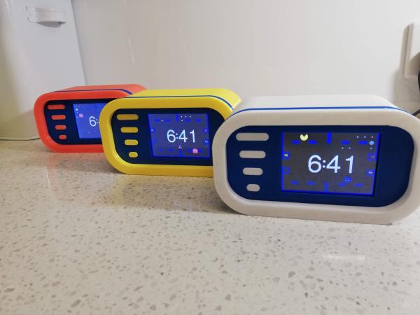
Motorized Camera Slider Gives Your Shots Style

We’ve all seen those smooth panning shots, which combined with some public domain beats, are a hallmark of the modern YouTube tech video. Recreating that style in your own productions is as easy as pointing your browser to Amazon and picking up a motorized camera slider, so long as you don’t mind parting with a few hundred bucks, anyway. But [PaweÅ‚ Spychalski] had a better idea. He decided to build his own camera slider and make it an open source project so others could spin up their own versions.

His design uses many components that have become popular and affordable thanks to the desktop 3D printer explosion, such as 2020 aluminum extrusion, LM8UU linear bearings, an 8 mm lead screw, and a NEMA 17 stepper motor. In fact, if you’ve got a broken 3D printer that you don’t know what to do with, stripping it for parts would get you a long way towards completing the BOM for this project.

To control the slider, [PaweÅ‚] is using an ESP32 and TMC2209 “StepStick” driver connected to an OLED display and a few buttons. As designed, a smartphone connected to a simple web page hosted by the ESP32 is the primary method of controlling the camera, but the buttons and display on the slider itself gives you a physical backup should you need it.

If you need something a bit more advanced than a linear slider, we’ve seen some impressive DIY motion rigs that can spin the camera around the target and produce some very professional looking shots.

Continue reading “Motorized Camera Slider Gives Your Shots Style”

Astronomical Clock Uses Your Spare Clock Motors

We’ll admit we are suckers for clock projects, and the more unusual, the better. We liked the look of [Peter Balch’s] astronomical clock, especially since it was handcrafted and was a relatively simple mechanism. [Peter] admits that it looks like an astronomical clock, but it isn’t the same as a complex instrument from medieval times. Instead, it uses several standard clock motors modified.

We didn’t quite follow some of the explanations for the rotation of the different elements, but the animated GIF cleared it all up. The inner and outer discs are geared at a 6:5 ratio. It takes 2 hours for the inner disc to make one rotation, meaning that every 12 hours the two discs will be back to where they began relative to one another.

Modifying the motors is fine work, requiring a good bit of disassembly and some glue. The electronics that make it tick are quite interesting. To drive the motors, a very specific pulse train is needed, but you also want to conserve battery as much as possible. A simple oscillator with a hex inverter drew more power than desired and an Arduino, even more so. A PIC12F629, though, could sleep a lot and do the job for a very low current consumption. The final clock should run a year on two AA cells.

Wooden Linear Clock Aided By GPS

The notion of segmenting and quantizing the day into discrete segments of time is perhaps one of the most human things we do. Heralding back to a simpler era when a day was just a progression of sunrise to sunset, [James Wilson] created a beautiful linear clock that shows time as progress throughout the day.

For previous projects, [James] had used nixie tubes but the headache of the inverters, high voltages, and tight spaces led him to instead use mini-LED’s. Two PCBs were manufactured, one as the display and one to hold the GNSS module as it works best when mounted horizontally to point at the sky. Two rows of 112 tightly packed LEDs make a great stand-in for bar graph style tubes and are are controlled by TLC5926 shift registers. The venerable STM32G0 was chosen as the microcontroller to power the clock. With the help of some approximating functions and the location provided by the GNSS module [James] had the position of the sun which he then could turn into a % of progress through the sky.

The enclosure was modeled after the mid-century modern look and made of several pieces of wood CNC’d and then glued together. Machining it out of a solid piece of wood would have been difficult as finding long enough end mills that could carve out the interior is tricky. We think the resulting clock looks wonderful and the walnut accents the maple nicely.

The writeup is highly detailed and we love the honest explanations of what choices were made and why. The code is available on GitHub. Or if perhaps you’d rather eschew the LED’s and go for something more physical there’s always this ratcheting linear clock to draw inspiration from.

ESP32 Turned Handy SWD Flasher For NRF52 Chips

Got an nRF52 or nRF51 device you need to flash? Got an ESP32 laying around collecting dust? If so, then firmware hacking extraordinaire [Aaron Christophel] has the open source code you need. His new project allows the affordable WiFi-enabled microcontroller to read and write to the internal flash of Nordic nRF52 series chips via their SWD interface. As long as you’ve got some jumper wires and a web browser, you’re good to go.

In the first video below [Aaron] demonstrates the technique with the PineTime smartwatch, but the process will be more or less the same regardless of what your target device is. Just connect the CLK and DIO lines to pins GPIO 21 and GPIO 19 of the ESP32, point your web browser to its address on the local network, and you’ll be presented with a straightforward user interface for reading and writing the chip’s flash.

As demonstrated in the second video, with a few more wires and a MOSFET, the ESP32 firmware is also able to perform a power glitch exploit on the chip that will allow you to read the contents of its flash even if the APPROTECT feature has been enabled. [Aaron] isn’t taking any credit for this technique though, pointing instead to the research performed by [LimitedResults] to explain the nuts and bolts of the attack.

We’re always excited when a message from [Aaron] hits the inbox, since more often that not it means another device has received an open source firmware replacement. From his earlier work with cheap fitness trackers to his wildly successful Bluetooth environmental sensor hacking, we don’t think this guy has ever seen a stock firmware that he didn’t want to immediately send to /dev/null.

Continue reading “ESP32 Turned Handy SWD Flasher For NRF52 Chips”

Pi Pico Game Boy Flash Cart Gets Slim RP2040 Upgrade

The story for this one starts a few months ago, when [John Green] released his PICO-GB project. His code allowed the Raspberry Pi Pico to stand in for a Game Boy cartridge, complete with a simple text menu that let the user select between ROMs that had been baked into the microcontroller’s firmware. The project was particularly notable for the fact that it was entirely a software solution; while a custom breakout cartridge made for a handy temporary solution, you could have permanently wired the Pico’s pins directly to the Game Boy’s cartridge connector if you wanted to.

PICO-GB running on the full-size Pi Pico

Then in early June, the RP2040 chip that powers the Pi Pico went up for sale in single unit quantities. That opened up the possibility of building the PICO-GB functionality into a cartridge small enough to actually fit inside the Game Boy. So [Martin “HDR” Refseth] got to work creating the slick cartridge PCB you’re seeing now.

The RP2040 is joined by a trio of Texas Instruments TXB0108 level shifters, and there’s a spot for adding a SPI flash chip. The RP2040 supports a maximum of 16 MB of external flash, but given the size of Game Boy games were generally measured in kilobytes, that shouldn’t pose much of a problem.

Looking ahead, the original PICO-GB documentation mentions enhancements like loading ROMs from SD card, as well as hardware additions like a real-time-clock for the more advanced games that supported it. We assume those concepts will become part of [Martin]’s PCB eventually, but these are still early days.

We’ve seen Game Boy cartridge emulation with a microcontroller in the past, but we’re exited to see how the unique capabilities of the Raspberry Pi Foundation’s custom silicon can improve the state-of-the-art.

[Thanks to Itay for the tip.]

Raspberry Pi Pico Oscilloscope

As you dive deeper into the world of electronics, a good oscilloscope quickly is an indispensable tool. However, for many use cases where you’re debugging low voltage, low speed circuits, that expensive oscilloscope is using only a fraction of its capabilities. As a minimalist alternative for these use cases [fhdm-dev] created Scoppy, a combination of firmware for the Raspberry Pi Pico and an Android app to create a functional oscilloscope.

As you would expect, the specifications are rather limited, capturing a maximum of 100 kpts at a speed of 500 kS/s shared between the two channels. Without some additional front end circuitry to protect the Pico, the input voltage is limited to 0-3.3 V. Neither the app nor the firmware is open source, and getting access to the second channel and removing ads requires a ~$3 in-app purchase. Even so, we can still think of plenty of practical uses for a ~$7 oscilloscope. If you do decide to add some front-end circuitry to change to voltage range, you can set them in the app, and switch between them by pulling certain GPIO pins high or low. The app has most of the basic oscilloscope features covered, continuous and single shot capture, adjustable trigger settings and a scalable waveform display.

Simple, cheap oscilloscopes like these have their place, but you start to understand why the “real” ones are so expensive when you see what goes into developing a high performance oscilloscope.

Test Your ‘Blue Pill’ Board For A Genuine STM32F103C8 MCU

With the market for STM32F103C8-based ‘Blue Pill’ boards slowly being overrun with boards that contain either a cloned, fake or outright broken chip, [Terry Porter] really wanted to have an easy, automated way to quickly detect whether a new board contains genuine STM32 silicon, or some fake that tries to look the part. After more than a year of work, the Blue Pill Diagnostics project is now ready for prime time.

We have covered those clone MCUs previously. It’s clear that some of those ‘Blue Pill’ boards obviously do not have a genuine STM32 MCU on them, as they do not have the STM32 markings on them, while others fake those markings on the package and identifying can be hard to impossible. Often only testing the MCU’s actual functionality can give clarity on whether it’s a real STM32 MCU.

These diagnostics allow one to test not only the 64 kB of Flash, but also the 64 kB of ‘hidden’ Flash that’s often found on these MCUs (rebadged 128 kB STM32F103 cores). It further checks the manufacturer JDEC code and uses a silicon bug in genuine STM32F1xx MCUs where the BGMCU_IDCODE cannot be read without either SWD or JTAG connected.

Another interesting feature of Blue Pill Diagnostics is using Mecrisp-Stellaris Forth as its foundation, which allows for easy access to a Forth shell via this firmware as well, not unlike MicroPython and Lua, only in a fraction of the Flash required by those. We have previously written about using Mecrisp-Stellaris in your projects.