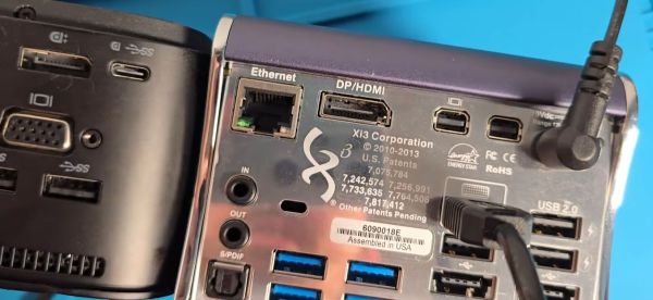
Op-Amp Challenge: MOSFETs Make This Discrete Op Amp Tick

When it comes to our analog designs, op-amps tend to be just another jellybean part. We tend to spec whatever does the job, and don’t give much of a thought as to the internals. And while it doesn’t make much sense to roll your own op-amp out of discrete components, that doesn’t mean there isn’t plenty to be learned from doing just that.

While we’re more accustomed to seeing [Mitsuru Yamada]’s digital projects, he’s no stranger to the analog world. In fact, this project is a follow-on to his previous bipolar transistor op-amp, which we featured back in 2021. This design features MOSFETs rather than BJTs, but retains the same basic five-transistor topology as the previous work, with a differential pair input stage, a gain stage, and a buffer stage. Even the construction of the module is similar, using his trademark perfboard and ultra-tidy wiring.

Also new is a flexible evaluation unit for these discrete op-amp modules. This very sturdy-looking circuit provides an easy way to configure the op-amp for testing in inverting, non-inverting, and transimpedance mode, selecting from a range of feedback resistors, and even provides a photodiode input. The video below shows the eval unit in action with the CMOS module, as well as highlights the excellent construction [Mitsuru Yamada] is known for.

Looking for some digital goodness? Check out the PERSEUS-8, a 6502 machine we wish had been a real product back in the day.

Continue reading “Op-Amp Challenge: MOSFETs Make This Discrete Op Amp Tick”

Big Tactile Button Is Silly But Cool

Every hacker is familiar with those teeny little tactile buttons that are so enjoyable to click over and over again. [ROBO HUB] has built a giant version as a tribute, and it works just like the real thing!

The giant button has been scaled up 20 times compared to the original. For simplicity’s sake, [ROBO HUB] designed this replica to use materials readily available around the home. Thanks to its cardboard construction, it’s easy to replicate with a minimum of tools. One need merely cut out the various sections before assembling them together with hot glue, with popsicle sticks serving as the legs. A juice bottle is used as the primary button itself, with aluminium foil serving as the contacts and rubber bands standing in for the spring.

It’s not the most useful button, given that it it’s quite fragile and has a weak spring return. However, it would be a great teaching tool to show students exactly what’s going on inside an actual button. As a bonus, it looks like it would be remarkably fun to pound on to activate some kind of massive air horn. Just an idea.

Continue reading “Big Tactile Button Is Silly But Cool”

The New Hotness

If there’s one good thing to be said about the chip shortage of 2020-2023 (and counting!) it’s that a number of us were forced out of our ruts, and pushed to explore parts that we never would have otherwise. Or maybe it’s just me.

Back in the old times, I used to be a die-hard Atmel AVR fan for small projects, and an STM32 fan for anything larger. And I’ll freely admit, I got stuck in my ways. The incredible abundance of dev boards in the $2 range also helped keep me lazy. I had my thing, and I was fine sticking with it, admittedly due to the low price of those little blue pills.

An IN-12B Nixie tube on a compact driver PCBAnd then came the drought, and like everyone else, my stockpile of microcontrollers started to dwindle. Replacements at $9 just weren’t an option, so I started looking around. And it’s with no small bit of shame that I’ll admit that I hadn’t been keeping up with the changes as much as I should have. Nowadays, it’s all ESP32s and RP2040s over here, and granted there’s a bit of a price bump, but the performance is there in abundance. But I can’t help feeling like I’m a few years back of the cutting edge.

So when I see work like what [CNLohr] and [Bitluni] are doing with the ultra-cheap CH32V003 microcontrollers, it makes me think that I need to start filling in gaps in my comfortable working-set of chips again. But how the heck am I supposed to keep up? And how do you? It took a global pandemic and silicon drought to force me out of my comfort zone last time. Can the simple allure of dirt-cheap chips get me out? We’ll see!

FET: Fun Endeavors Together

Last time, we’ve looked over FET basics, details, nuances and caveats. Basics aren’t all there is to FETs, however – let’s go through real-world uses, in all their wonderful variety! I want to show you a bunch of cool circuits where a friendly FET, specifically a MOSFET, can help you – and, along the way, I’d also like to introduce you to a few FETs that I feel like you all could have a good long-term friendship with. If you don’t already know them, that is!

Driving Relays

Perhaps, that’s the single most popular use for an NPN transistor – driving coils, like relays or solenoids. We are quite used to driving relays with BJTs, typically an NPN – but it doesn’t have to be a BJT, FETs often will do the job just as fine! Here’s an N-FET, used in the exact same configuration as a typical BJT is, except instead of a base current limiting resistor, we have a gate-source resistor – you can’t quite solder the BJT out and solder the FET in after you have designed the board, but it’s a pretty seamless replacement otherwise. The freewheel (back EMF protection) diode is still needed for when you switch the relay and the coil produces wacky voltages in protest, but hey, can’t have every single aspect be superior.

The reason you can drive it the same way is quite simple: in the usual NPN circuit, the relay is driven by a 3.3 V or a 5 V logic level GPIO, and for small signal FETs, that is well within Vgs. However, if your MCU has 1.8 V GPIOs and your FET’s Vgs doesn’t quite cut it, an NPN transistor is a more advantageous solution, since that one will work as long as you can source the whatever little current and the measly 0.7 V needed.

Continue reading “FET: Fun Endeavors Together”

Hinges Live Inside 3D Prints

Since desktop 3D printers have become more common, we’ve seen dramatic shifts in all kinds of areas such as rapid prototyping, antique restoration, mass production of consumer goods, or even household repairs that might not have been possible otherwise. There are a lot of unique manufacturing methods that can be explored in depth with a 3D printer as well, and [Slant 3D] demonstrates how one such method known as the living hinge can be created with this revolutionary new tool.

Living hinges, unlike a metal hinge you might pick up at a hardware store, are integrated into the design of the part and made of the same material. Typically found in plastic containers, they allow for flexibility while keeping parts count and cost low. The major downside is that they create stresses in the materials when used, so their lifespan is finite. But there are a number of ways to extend their life, albeit with a few trade-offs.

The first note is to make sure that you’re using the right kind of plastic, but after that’s taken care of [Slant 3D] builds a few flexible parts starting with longer circular-shaped living hinge which allows greater range of motion and distributes the forces across a wider area, at a cost of greater used space and increased complexity. A few other types of living hinges are shown to use less space in some areas, but make the hinges only suitable for use in other narrower applications.

One of the more interesting living hinges he demonstrates is one that’s more commonly seen in woodworking, known there as a kerf bend. By removing strips of material from a sheet, the entire sheet can be rotated around the cuts. In woodworking this is often done by subtracting material with a CNC machine or a laser cutter, but in 3D printing the voids can simply be designed into the part.

Continue reading “Hinges Live Inside 3D Prints”

Compressed Air Keeps Screws Moving Through Modular Production System

If there’s an unsung hero of manufacturing, it’s the engineer who figures out how to handle huge numbers of small parts. It’s one thing to manually assemble something, picking each nut, bolt, and washer by hand. It’s another thing to build a machine that can do the same thing, but thousands of times in a row, ideally without making mistakes.

Most of us don’t need that level of automation in our processes, but when you do, it results in some interesting challenges. Take this pneumatic screw accelerator that [Christopher Helmke] designed for his modular production system. One of the custom machines in his system is a screw counter, which uses a magnetic wheel to feed screws — or nuts or washers — from a hopper, orient them correctly, and drop them into an output chute. While the counting bit worked quite well, parts would only go so far under the force of gravity in the clear vinyl tube used to connect the counter to the next process.

[Christopher]’s solution was simple but effective. His first prototype simply injects compressed air into the parts feed tube, which pushes the screws through the tubing. It works surprisingly well, propelling the parts through quite a long length of tubing, handling twisting paths easily and even working against gravity. Version 2 integrated the accelerator and a re-orienting fixture into a single part, which mates with a magazine that holds a large number of screws.

There are a lot of interesting features [Christoper] built into these simple parts that are worth keeping in mind. Our favorite is printing channels to guide small cable ties around the tubing to clamp it into the accelerator. We’ll be keeping that trick in mind.

Continue reading “Compressed Air Keeps Screws Moving Through Modular Production System”

FET: The Friendly Efficient Transistor

If you ever work with a circuit that controls a decent amount of current, you will often encounter a FET – a Field-Effect Transistor. Whether you want to control a couple of powerful LEDs, switch a USB device on and off, or drive a motor, somewhere in the picture, there’s usually a FET doing the heavy lifting. You might not be familiar with how a FET works, how to use one and what are the caveats – let’s go through the basics.

Here’s a simple FET circuit that lets you switch power to, say, a USB port, kind of like a valve that interrupts the current flow. This circuit uses a P-FET – to turn the power on, open the FET by bringing the GATE signal down to ground level, and to switch it off, close the FET by bringing the GATE back up, where the resistor holds it by default. If you want to control it from a 3.3 V MCU that can’t handle the high-side voltage on its pins, you can add a NPN transistor section as shown – this inverts the logic, making it into a more intuitive “high=on, low=off”, and, you no longer risk a GPIO!

This circuit is called a high-side switch – it enables you to toggle power to a device at will through a FET. It’s the most popular usecase for a FET, and if you’re wondering more about high-side switches, I highly recommend this brilliant article by our own [Bil Herd], where he shows you high-side switch basics in a simple and clear way. For this article, you can use this schematic as a reference of how FETs are typically used in a circuit.

Continue reading “FET: The Friendly Efficient Transistor”