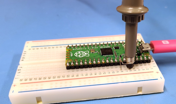
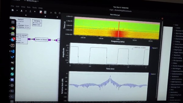
Pi Saves Vintage Mac Case From A Watery Grave

Like many before it, this Mac 512K case was originally slated to get turned into a kitschy desktop aquarium. But its owner never found the time to take on the project, and instead gave it to [Tony Landi]. Luckily, he decided to forgo the fish and instead outfit the case with a new LCD display and Raspberry Pi to emulate Mac OS 7.5.

Mounting the LCD and associated electronics.

In the video after the break, [Tony] walks viewers through the process of mounting the new components into the nearly 30+ year old enclosure. Things are naturally made a lot easier by the fact that the modern electronics take up a small fraction of the Mac’s internal volume. Essentially the only things inside the case are the 10 inch 4:3 LCD panel, the Raspberry Pi, and a small adapter that turns the Mac’s pre-ADB keyboard into standard USB HID.

[Tony] had to design a 3D printed adapter to mount the modern LCD panel to the Mac’s frame, and while he was at it, he also came up with printable dummy parts to fill in the various openings on the case that are no longer necessary. The mock power switch on the back and the static brightness adjustment knob up front are nice touches, and the STLs for those parts will certainly be helpful for others working on similar Mac conversions.

With the hardware out of the way, [Tony] switches gears and explains how he got the emulated Mac OS environment up and running on the Raspberry Pi. Again, even if you don’t exactly follow his lead on this project, his thorough walk-through on the subject is worth a watch for anyone who wants to mess around with Apple software from this era.

Continue reading “Pi Saves Vintage Mac Case From A Watery Grave”

Rack ’em Stack ’em Raspberry Pi Controller Board

It isn’t that hard to assemble an array of Raspberry Pi boards and there are several reasons you might want to do so. The real trick is getting power to all of them and cooling all of them without having a mess of wires and keeping them all separated. The ClusterCTRL stack lets you stack up to five Raspberry Pi boards together. The PCB aligns vertically along the side of the stack of Pis with sockets for each pin header. Using a single 12 to 24V supply, it provides power for each board, a USB power connection, and provisions for two fans. There is also a USB port to control the fans and power.

There’s also a software component to deliver more granular control. Without using the software, the PI’s power on in one second and monitor a GPIO pin to control the fans. With the software, you can turn on or off individual nodes, gang the two fans to turn on together, and even add more stacks.

There is a case that you can print from STL files, although you can buy them preprinted on the Tindie listing where the bulk of information on ClusterCTRL is found. You could also have a 3D printing vendor run off a copy for you if you’d rather.

The power supply is a 10A 5.1V DC to DC converter. That works out to 2A per Pi and 51W total. The power supply for the input, then, needs to be enough to cover 51W, the power for the fans, and some overhead for regulator inefficiency and other small overhead.

We’ve seen a lot of Pi clusters over the years including one that is a good learning tool for cluster management. Of course, there’s always the Oracle cluster with 1,060 boards, which is going to take a bigger power supply.

Folding Raspberry Pi Enclosure Prints In One Piece, No Screws In Sight

[jcprintnplay] has challenged himself to making Raspberry Pi cases in different ways, and his Fold-a-Pi enclosure tries for a “less is more” approach while also leveraging the strong points of 3D printing. The enclosure prints as a single piece in about 3 hours, and requires no additional hardware whatsoever.

The design requires no screws or other fasteners, and provides a mounting hole for a fan as well as some holes for mounting the enclosure itself to something. All the ports and headers are accessible, and the folding one-piece design is not just a gimmick; in a workshop situation where the Pi needs to be switched out or handled a lot, it takes no time at all to pop the Raspberry Pi in and out of the enclosure.

Microsoft’s 3D Builder has a pretty useful measurement tool for STLs.

[James] points out that the trick with a print-in-place hinge like this is leaving enough space between the parts so that the two pieces aren’t fused together, but not so much space that the print fails. He doesn’t go into detail about how much space worked or didn’t work, but an examination of the downloadable model shows that the clearance used looks like 0.30 mm, intended to be printed with a 0.4 mm nozzle.

[James] also demonstrates the value of being able to do quick iterations on a design when prototyping. In a video (embedded below) The first prototype had the hinge not quite right. In the second prototype there was a lack of clearance when closing. The third one solved both and shows the final design.

Continue reading “Folding Raspberry Pi Enclosure Prints In One Piece, No Screws In Sight”

Raspberry Pi Gets PATA/IDE Drive Via GPIO Header

By and large, the Raspberry Pi is a computer that eschews legacy interfaces. Primarily relying on SD cards for storage and USB ports for further expansion, magnetic hard drives are a rare sight. However, [Manawyrm] decided that some 40-pin goodness was in order, and set to making a PATA IDE adapter for the platform.

To achieve the task of interfacing now-vintage IDE devices with the Raspberry Pi, [Manawyrm] elected to use the single board computer’s GPIO pins to get the job done. 23 pins are required, with 16 used for the data bus, with the rest dedicated to address lines, strobes, and other features.

The adapter is no speed demon, netting 800 KiB/s on reads and 500 KiB/s on writes with a Raspberry Pi 4. The main bottleneck comes from relying on libgpiod, which [Manawyrm] readily admits is designed for general IO tasks, not data transfers. Despite this, it’s still fast enough to play an audio CD from an IDE CD-ROM drive without skipping. A kernel build is required, however, as Raspberry Pis are unsurprisingly not configured to use ATA disks by default.

Obviously, more serious applications would substitute a dedicated USB hard disk adapter or give the Raspberry Pi a PCI-express (PCIe) card for sata drives instead, but that doesn’t discount the fun inherent in the build. While it may be slow, it shows that talking to PATA hard disks is actually quite straightforward when you understand the basics. Of course, if you want to do the opposite, and have your Raspberry Pi emulate a PATA disk, that’s possible too. Video after the break.

Continue reading “Raspberry Pi Gets PATA/IDE Drive Via GPIO Header”

The Zero Terminal 3: A Pop-Out Keyboard Linux Computer In Your Pocket

The mobile phone revolution has delivered us attractively packaged and convenient computing in our pockets, but without the easy hackability we like in our community. Meanwhile the advent of single board computers has given us affordable super-powerful hardware that can run a very capable GNU/Linux operating system and fulfill all our hackable computing needs. Combine the two though? Plenty have tried, few have succeeded in making something as slick as the former with the open power of the latter. Fine if you like your portable devices to have a cyberdeck vibe, but maybe not something you’d take into the boardrooom. Never fear though, for [N-O-D-E] have the solution, in version 3 of the Zero Terminal. It’s the ultimate in Raspberry Pi based handheld computing, and it resembles a slightly chunky mobile phone.

At its heart is a Waveshare OLED 5.5″ touch screen, on the back owhich is mounted a PCB that carries a USB hub and power circuitry. A Pi Zero is mounted directly to this, and a cleverly designed HDMI adapter board interfaces it to the display. The power board is a generic one, the one designed for the PCB proved difficult to hand solder. There’s a very smartly designed case to give it that mobile phone feel, and on the back are a set of sockets with all the relevant Pi connections. This opens the possibility of some exciting add-ons, the first of which is a sliding keyboard similar to those on early Android phones. The ‘board is based on a [Bobricius] design, though sadly isn’t quite working yet.

As you can see in the video below the break, this is about as slick a mobile Pi as it’s possible to get. [N-O-D-E], we want one. Just take our money!

Continue reading “The Zero Terminal 3: A Pop-Out Keyboard Linux Computer In Your Pocket”

Unbricking A $2,000 Exercise Bike With A Raspberry Pi Zero And Bluetooth Hacks

Really, how did we get the point in this world where an exercise bike can be bricked? Such was the pickle that [ptx2] was in when their $2,000 bike by Flywheel Home Sports was left without the essential feature of participating in virtual rides after Peloton bought the company. The solution? Reverse engineer the bike to get it working with another online cycling simulator.

Sniffing Flywheel Bluetotooth packets with Bluetility

We have to admit we weren’t aware of the array of choices that the virtual biking markets offers. [ptx2] went with Zwift, which like most of these platforms, lets you pilot a smart bike through virtual landscapes along with the avatars of hundreds of other virtual riders. A little Bluetooth snooping with Bluetility let [ptx2] identify the bytes in the Flywheel bike’s packets encoding both the rider’s cadence and the power exerted, which Zwift would need, along with the current resistance setting of the magnetic brake.

Integration into Zwift was a matter of emulating one of the smart bikes already supported by the program. This required some hacking on the Cycling Power Service, a Bluetooth service that Zwift uses to talk to the bike. The final configuration has a Raspberry Pi Zero W between the Flywheel bike and the Zwift app, and has logged about 2,000 miles of daily use. It still needs a motor to control the resistance along the virtual hills and valleys, but that’s a job for another day.

Hats off to [ptx2] for salvaging a $2,000 bike for the price of a Pi and some quality hacking time, and for sticking it to The Man a bit. We have to say that most bike hacks we see around here have to do with making less work for the rider, not more. This project was a refreshing change.

[Featured images: Zwift, Flywheel Sports]

[via r/gadgets]

Facial Detection With Pi + MATLAB

[Monica] wanted to try a bit of facial detection with her Raspberry Pi and she found some pretty handy packages in MATLAB to help her do just that. The packages are based on the Viola-Jones algorithm which was the first real-time object detection framework for facial detection.

She had to download MATLAB’s Raspbian image to allow the Pi to interpret MATLAB commands over a custom server. That setup is mostly pretty easy and she does a good job walking you through the setup on her project page.

With that, now she can control the Pi in MATLAB: configure the camera, toggle GPIO, etc. The real fun comes with the facial detection program. In addition to opening up a live video feed of the Pi camera, the program outputs pixel data. [Monica] was mostly just testing the stock capabilities, but wants to try detecting other objects next. We’ll see what cool modifications she’s able to come up with.

If MATLAB doesn’t quite fit your taste, we have a slew of facial detection projects on Hackaday.