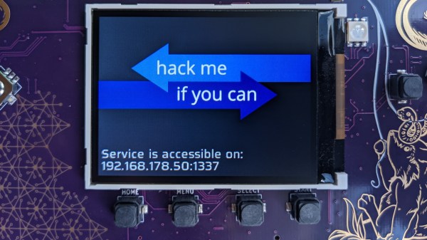
Remoticon 2021 // Jeroen Domburg [Sprite_tm] Hacks The Buddah Flower

Nobody likes opening up a hacking target and finding a black epoxy blob inside, but all hope is not lost. At least not if you’ve got the dedication and skills of [Jeroen Domburg] alias [Sprite_tm].

It all started when [Big Clive] ordered a chintzy Chinese musical meditation flower and found a black blob. But tantalizingly, the shiny plastic mess also included a 2 MB flash EEPROM. The questions then is: can one replace the contents with your own music? Spoiler: yes, you can! [Sprite_tm] and a team of Buddha Chip Hackers distributed across the globe got to work. (Slides here.)

[Jeroen] started off with binwalk and gets, well, not much. The data that [Big Clive] dumped had high enough entropy that it looks either random or encrypted, with the exception of a couple tiny sections. Taking a look at the data, there was some structure, though. [Jeroen] smelled shitty encryption. Now in principle, there are millions of bad encryption methods out there for every good one. But in practice, naive cryptographers tend to gravitate to a handful of bad patterns.

Bad pattern number one is XOR. Used correctly, XORing can be a force for good, but if you XOR your key with zeros, naturally, you get the key back as your ciphertext. And this data had a lot of zeros in it. That means that there were many long strings that started out the same, but they seemed to go on forever, as if they were pseudo-random. Bad crypto pattern number two is using a linear-feedback shift register for your pseudo-random numbers, because the parameter space is small enough that [Sprite_tm] could just brute-force it. At the end, he points out their third mistake — making the encryption so fun to hack on that it kept him motivated!

Decrypted, the EEPROM data was a filesystem. And the machine language turned out to be for an 8051, but there was still the issue of the code resident on the microcontroller’s ROM. So [Sprite_tm] bought one of these flowers, and started probing around the black blob itself. He wrote a dumper program that output the internal ROM’s contents over SPI. Ghidra did some good disassembling, and that let him figure out how the memory was laid out, and how the flow worked. He also discovered a “secret” ROM area in the chip’s flash, which he got by trying some random functions and looking for side effects. The first hit turned out to be a memcpy. Sweet.

[Neil555]’s Rosetta Stone
Meanwhile, the Internet was still working on this device, and [Neil555] bought a flower too. But this one had a chip, rather than a blob, and IDing this part lead them to an SDK, and that has an audio suite that uses a derivative of WMA audio encoding. And that was enough to get music loaded into the flower. (Cue a short rick-rolling.) Victory!

Well, victory if all you wanted to do was hack your music onto the chip. As a last final fillip, [Sprite_tm] mashed the reverse-engineered schematic of the Buddha Flower together with [Thomas Flummer]’s very nice DIY Remoticon badge, and uploaded our very own intro theme music into the device on a badge. Bonus points? He added LEDs that blinked out the LSFR that were responsible for the “encryption”. Sick burn!

Editor’s Note: This is the last of the Remoticon 2 videos we’ve got. Thanks to all who gave presentations, to all who attended and participated in the lively Discord back channel, and to all you out there who keep the hacking flame alive. We couldn’t do it without you, and we look forward to a return to “normal” Supercon sometime soon.

Remoticon 2021 // Rob Weinstein Builds An HP-35 From The Patent Up

Fifty years ago, Hewlett-Packard introduced the first handheld scientific calculator, the HP-35. It was quite the engineering feat, since equivalent machines of the day were bulky desktop affairs, if not rack-mounted. [Rob Weinstein] has long been a fan of HP calculators, and used an HP-41C for many years until it wore out. Since then he gradually developed a curiosity about these old calculators and what made them tick. The more he read, the more engrossed he became. [Rob] eventually decided to embark on a three year long reverse-engineer journey that culminated a recreation of the original design on a protoboard that operates exactly like the original from 1972 (although not quite pocket-sized). In this presentation he walks us through the history of the calculator design and his efforts in understanding and eventually replicating it using modern FPGAs.

The HP patent ( US Patent 4,001,569 ) contains an extremely detailed explanation of the calculator in nearly every aspect. There are many novel concepts in the design, and [Rob] delves into two of them in his presentation. Early LED devices were a drain on batteries, and HP engineers came up with a clever solution. In a complex orchestra of multiplexed switches, they steered current through inductors and LED segments, storing energy temporarily and eliminating the need for inefficient dropping resistors. But even more complicated is the serial processor architecture of the calculator. The first microprocessors were not available when HP started this design, so the entire processor was done at the gate level. Everything operates on 56-bit registers which are constantly circulating around in circular shift registers. [Rob] has really done his homework here, carefully studying each section of the design in great depth, drawing upon old documents and books when available, and making his own material when not. For example, in the course of figuring everything out, [Rob] prepared 338 pages of timing charts in addition to those in the patent. Continue reading “Remoticon 2021 // Rob Weinstein Builds An HP-35 From The Patent Up”

Tricking A Smart Meter Into Working On The Bench

When the widget you’re working on is powered by a battery or a USB charger, running it on the bench is probably pretty safe. But when the object of your reverse-engineering desire is a residential electrical meter, things can get a little dicey.

Not that this elevated danger level has kept [Hash] from exploring the mysteries presented by smart meters. Still, with a desire to make things a little safer, he came up with a neat trick for safely powering electrical meters on the bench. [Hash] found that the internal switch-mode power supply on the meter backplane was easy enough to back-feed with a 12-volt bench supply, rather than supplying the meter with the full 240-volt AC supply it normally gets when plugged into a meter base (these are meters for the North American market, where split-phase 240-volt is the norm for residential connections.) But that wasn’t enough for the meter — it powered up, but stayed in a reset state without fully booting. Something more was needed to bring the meter fully to life.

That something proved to be a small AC signal. Normally, a resistor network divides the 240-volt supply down to about 3 volts, which is used by the sensing circuit in the meter. [Hash] found that injecting a 60-Hz, 600-mV sine wave signal with about a 3-volt DC bias into the sensing circuit was enough to spoof the meter into thinking it’s plugged into the meter base. The video below has a walkthrough of the hack, and some nice shots of the insides of the meters he’s been working with.

[Hash] has been working with these meters for a while now, and some of the stuff he’s learned is pure gold. Be sure to check out his 2021 Remoticon talk on meter hacking for all the fascinating details.

Continue reading “Tricking A Smart Meter Into Working On The Bench”

Version 1.8 of the 80386 ISA SBC in its assembled glory. (Credit: Alexandru Groza)

Building Your Own 80386DX ISA Single Board Microcomputer

Having grown up with 386-level systems during the early 90s like so many of us, [Alexandru Groza] experienced an intense longing to experience the nostalgia of these computer systems from an interesting angle: by building his own 80386DX-based single board computer. Courtesy of the 16-bit ISA form factor, the entire system fits into a 16-bit ISA backplane which then provides power and expansion slots for further functionality beyond what is integrated on the SBMC card.

Having started the project in 2019, it is now in the home stretch towards completion. Featuring an 80386DX and 80387DX FPU alongside 128 kB of cache and a grand total of 32 MB of RAM, an OPTi chipset was used to connect with the rest of the system alongside the standard 8042-class PS/2 keyboard and mouse controller. A large part of the fun of assembling such a system is that while the parts themselves are easy enough to obtain, finding datasheets is hard to impossible for some components.

Undeterred, some reverse-engineering of signaling on functional mainboards was sufficient to fill in the missing details. Helpfully, [Alexandru] provides the full schematics and BOM of the resulting board and takes us along with bootstrapping the system after obtaining the PCBs and components. After an initial facepalm moment due to an incorrectly inserted (and subsequently very dead) CPU and boot issues, ultimately [Alexandru] gave up on the v1.6 revision of the board

Fortunately the v1.8 revision with a logic analyzer led to a number of discoveries that has led to the system mostly working, minus what appears to be DMA-related issues. Even so, it is a remarkable achievement that demonstrates the complexity of these old systems.

Mockup of an LG SmartTV, showing the webOS logo, saying "debug status: DEBUG, SIGN Key: PRODKEY, Access USB Status: 0/100(C)", and showing a console prompt on the bottom.

What’s That AccessUSB Menu In My LG SmartTV?

One boring evening, [XenRE] was looking through service menus on their LG Smart TV (Russian, Google Translate), such menus accessible through use of undocumented IR remote codes. In other words, a fairly regular evening. They noticed an “Access USB Status” entry and thought the “Access USB” part looked peculiar. A few service manuals hinted that there’s a service mode you could access with an adapter made out of two back-to-back PL2303 USB-UART adapters – a few female-female jumper wires later, serial prompt greeted our hacker, and entering ‘debug’ into the prompt responded with some text, among it, “Access USB is NOT opened!!!”.

[XenRE] found the WebOS firmware for the TV online, encrypted and compressed into a proprietary LG .epk format, but liberated with an open-source tool. A few modules referred to AccessUSB there, and one detour into investigating and explaining WebOS USB vendor lock-in implementation later, they programmed an STM32 with the same VID and PID as the mythical AccessUSB device found in relevant WebOS modules decompiled with IDA. By this point, AccessUSB could safely be assumed to be a service mode dongle. The TV didn’t quite start beeping in a different pattern as we’d expect in a sci-fi movie, but it did notify about a “new USB device” – and started asking for a 6-symbol service menu password instead of a 4-symbol one. Continue reading “What’s That AccessUSB Menu In My LG SmartTV?”

The BluePill board used for this hack, wired to the DYMO RFID reader, after all the wires for this hack have been soldered onto the BluePill board.

#FreeDMO Gets Rid Of DYMO Label Printer DRM

DYMO 550 series printer marketing blurb says “The DYMO® LabelWriter® 550 Turbo label printer comes with unique Automatic Label Recognition™”, which, once translated from marketing-ese, means “this printer has DRM in its goshdarn thermal stickers”. Yes, DRM in the stickers that you typically buy in generic rolls. [FREEPDK] didn’t like that, either, and documents a #FreeDMO device to rid us of yet another consumer freedom limitation, the true hacker way.

The generic BluePill board and two resistors are all you need, and a few extra cables make the install clean and reversible – you could definitely solder to the DYMO printer’s PCBs if you needed, too. Essentially, you intercept the RFID reader connections, where the BluePill acts as an I2C peripheral and a controller at the same time, forwarding the data from an RFID reader and modifying it – but it can also absolutely emulate a predetermined label and skip the reader altogether. If you can benefit from this project’s discoveries, you should also take a bit of your time and, with help of your Android NFC-enabled phone, share your cartridge data in a separate repository to make thwarting future DRM improvements easier for all of us. Continue reading “#FreeDMO Gets Rid Of DYMO Label Printer DRM”

[Ken Shirriff] Takes A Bite Of The Apple-I

The Apple-I was a far cry from Apple’s later products. A $666 single-board computer, the product had some unique design features including using a shift register for video memory to save money. The shift registers of the day required high-current clock pulses that ranged from -11 to 5V and there was a DS0025 clock driver chip to handle the job. [Ken Shirriff] takes the unusual chip apart for us in a recent blog post.

The use of a shift register as memory isn’t a new idea. Really old computers like EDSAC used mercury delay lines as memory which was essentially a physical shift register. In those cases, the ALU and other processing only had to deal with a bit at a time, further simplifying things. For the Apple, there were seven shift registers to store 6-bits of display data and a cursor position. The 6 bits of character data drove — indirectly — a character generator ROM to convert the data into dots for the display.

Driving all those shift register flip flops requires a lot of clock current, so the DS0025 uses an unusual transistor design. There are 24 separate emitters in two groups. It acts like a large transistor, but you could also consider it as two 12-emitter transistors or 24 separate transistors in parallel. The metal wiring, interestingly enough, tapers because at the start of the conductor, the current for all 12 sub-transistors flows, but by the end, it is only the current for the last sub-transistor, so the conductor doesn’t have to be as wide. In addition, the two transistors have to have matched resistance which requires careful design so the transistors turn on at the same time.

The final result is an inverter that can provide 1.5 amps. This current helps overcome the relatively large capacitance in the shift register’s clock line. The clock rate was 1 MHz and the load capacitance was about 150 picofarads.

We enjoy [Ken’s] posts ranging from mysteries to space hardware. It is always interesting to see what is inside these devices or, at least, what was in the old devices we’ve all seen.