Reverse Engineering Quadcopter Protocols

Necessity is the mother of invention, but cheap crap from China is the mother of reverse engineering. [Michael] found a very, very cheap toy quadcopter in his local shop, and issued a challenge to himself. He would reverse engineer this quadcopter’s radio protocol. His four-post series of exploits covers finding the right frequency for the radio, figuring out the protocol, and building his own remote for this cheap toy.

[Michael] was already familiar with the capabilities of these cheap toys after reading a Hackaday post, and the 75-page, four language manual cleared a few things up for him. The ‘Quadro-Copter’ operated on 2.4GHz, but did not give any further information. [Michael] didn’t know what channel the toy was receiving on, what data rate, or what the header for the transmission was. SDR would be a good tool for figuring this out, but thanks to Travis Goodspeed, there’s a really neat trick that will put a 2.4GHz nRF24L01+ radio into promiscuous mode, allowing [Michael] to read the transmissions between the transmitter and quadcopter. This code is available on [Michael]’s github.

A needle in an electromagnetic haystack was found and [Michael] could listen in on the quadcopter commands. The next step was interpreting the ones and zeros, and with the help of a small breakout board and soldering directly to the SPI bus on the transmitter, [Michael] was able to do just that. By going through the nRF24 documentation, he was able to suss out the pairing protocol and read the stream of bytes that commanded the quadcopter.

What [Michael] was left with is a series of eight bytes sent in a continuous stream from the transmitter to the toy. These bytes contained the throttle, yaw, pitch, roll, and a ‘flip’ settings, along with three bytes of ‘counters’ that didn’t seem to do anything.  With that info in hand, [Michael] took an Arduino Nano, an nRF04L01+ transceiver, and a Wii nunchuck to build his own transmitter. If you’re looking for a ‘how to reverse engineer’ guide, it generally doesn’t get better than this.

You can check out a video of [Michael] flying his Wiimoted quadcopter below.
Continue reading “Reverse Engineering Quadcopter Protocols”

AVR Vs PIC, Round 223: Fight!

Get ready to rumble! [Thierry] made the exact same Hello-World-esque project with two microcontrollers (that are now technically produced by the same firm!) to see how the experience went.

It’s not just an LED-blinker, though. He added in a light-detection function so that it only switches on at night. It uses the Forest Mims trick of reverse-biasing the LED and waiting for it to discharge its internal capacitance. The point is, however, that it gives the chip something to do instead of simply sleeping.

Although he’s an AVR user by habit, [Thierry] finds in favor of the PIC because it’s got a lower power draw both when idling and when awake and doing some computation. This is largely because the PIC has an onboard low-power oscillator that lets it limp along at 32 kHz, but also because the chip has a lower power consumption in general. In the end, it’s probably a 10% advantage to the PIC on power.

If you’re competent with one of the two chips, but not the other, his two versions of the same code would be a great way to start familiarizing yourself with the other. We really like his isDarkerThan() function which makes extensive use of sleep modes on both chips during the LED’s discharge period. And honestly, at this level the code for the two is more similar than different.

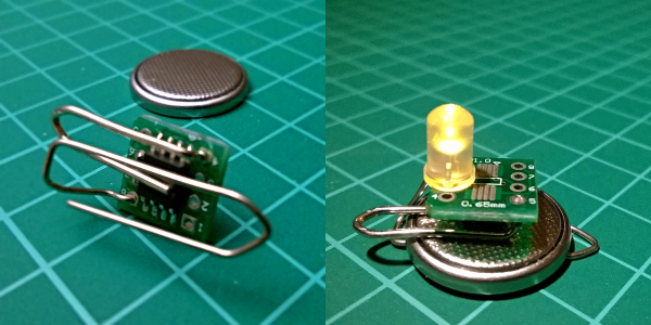
(Oh, and did you notice [Thierry]’s use of a paper clip as a coin-cell holder? It’s a hack!)

Surprisingly, we’ve managed to avoid taking a stray bullet from the crossfire that occasionally breaks out between the PIC and AVR fans. We have covered a “shootout” before, and PIC won that round too, although it was similarly close. Will the Microchip purchase of Atmel calm the flames? Let’s find out in the comment section. We have our popcorn ready!

PinJig Soldering Clamp Has Pins Seized By Airport Security

There’s an old adage that when performing a live demo, previously working hacks will mysteriously go awry. In this case, the hardware demo was doomed before it ever arrived at the conference.

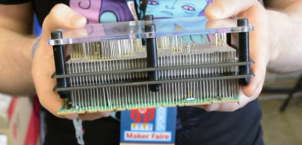
PinJig is an interesting take on though-hole soldering. As its name indicates, it’s a jig which holds through-hole components in place as the board is flipped on its side (or even upside down). This is accomplished by 2000 steel pins which are locked in place after being nestled around all of the board’s components. Unfortunately, carrying this prototype onto an international flight didn’t work out. [Niall Barrett] told us that on his way from Ireland to Bay Area Maker Faire he was required to ditch the 3-inch steel pins that make up the jig, or not get on the plane.

Continue reading “PinJig Soldering Clamp Has Pins Seized By Airport Security”

EV History: The Lightning Precedes The Thunder

In 1988, a bunch of engineers from Hotzenwald, Germany, came together and decided that it is time for the future of mobility: A new, more modern and environmentally friendly car should put an end to fossils and emissions while still being fun to drive. “It should become a new kind of car. Smaller, lighter, cleaner – and more beautiful” is how future CEO Thomas Albiez described his mission. For the first time in automotive history, this series car would be designed as an all-electric vehicle from the start and set a new standard for mobility. The project was given the codename “Hotzenblitz” (“Hotzen Bolt”) to indicate how the idea came to them: Like a lightning bolt. The snarky regional term also came with a double meaning: Imaginary lightning bolts, used for insurance fraud.

hotzenblitz_chassis
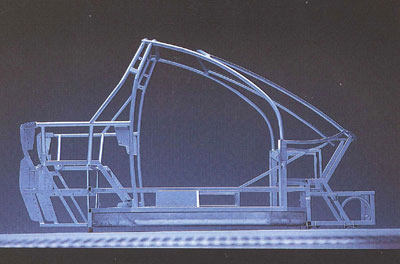
Hotzenblitz frame construction (origin unknown, image source)

Unnoticed by the rest of the world, they founded Hotzenblitz Mobile. Industrial Designer Harold Schurz was contracted to design the chassis for the Hotzenblitz, which was then modeled into a prototype chassis. The self-funded team moved fast. An external motorsports company helped to develop the tubular steel frame, and soon their vision took on shape. After the team had fitted a motor and transmission into the frame, CEO Thomas Albiez himself installed the traction battery and drive train. The team felt confident with the result, and in July 1990, during an open house day in the office, they somewhat spontaneously decided to call Green Tech entrepreneur and chocolate mogul Alfred Ritter.

Alfred Ritter had experienced financial losses after the Chernobyl Disaster. Many agricultural regions, including several hazelnut plantations that were vital to Alfred’s chocolate business, were irreversibly lost to the fallout contamination. It was then when he turned to the green energy business, founding the Paradigma group to manufacture solar collector systems and pellet heaters. When Thomas and the team called, Alfred jumped on the idea of an electric car. In the same year, Alfred Ritter and his sister Marli Hoppe-Ritter became shareholders in the company and helped to finance the future of the Hotzenblitz.

Continue reading “EV History: The Lightning Precedes The Thunder”

Homemade Smart Glasses Shows Why Smart Glasses Are Hard

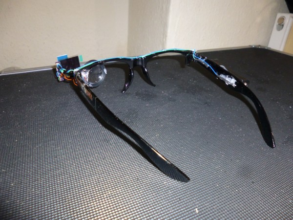
[Harris Shallcross] decided to build a pair of smart glasses and recently completed a first prototype of his project ‘Ochi’ – an STM32 based, BLE-connected, OLED eyeglass display. There are of course several homebrew smart glasses projects out there; many are more polished-looking and nearly all of them also display information from a smartphone over Bluetooth. This one is interesting partly because it highlights many of the design challenges that smart glasses and other near-eye displays face. It also demonstrates the iterative development process: begin by getting something working to learn what does and doesn’t cut it at a basic level, and don’t optimize prematurely; let the process bring problems to the surface.

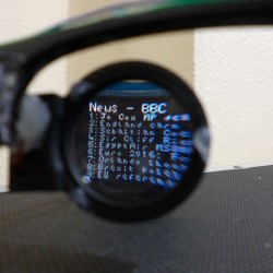
Ochi-1 Smart Glasses BBC feed SquareFor his project, [Harris Shallcross] used a small 0.95″ diagonal 96×64 color OLED as the display. The lens is from a knockoff Google Cardboard headset, and is held in a 3D printed piece that slides along a wire rail to adjust focus. The display uses a custom font and is driven by an STM32 microcontroller on a small custom PCB, with an HM11 BLE module to receive data wirelessly. Power is provided by a rechargeable lithium-ion battery with a boost converter. An Android app handles sending small packets of data over Bluetooth for display. The prototype software handles display of time and date, calendar, BBC news feed, or weather information.
Devices like these have a lot to deal with. Weight and distribution of that weight is a concern, the size and comfort of the optics is important, and displaying data on a small OLED is only part of the battle – choosing what information to display and when are vital to the device being actually useful in any way, otherwise it’s just a tech demo.

This project set out to show whether it was possible to use the parts listed to make a glasses mounted smart display that was at least somewhat functional, and the software to support it. Clearly, [Harris Shallcross] succeeded at that, but what really showcases the development process is his list of improvements – what he decided needs to go into a second version, and why. One of those goals is to improve the optics; perhaps there’s something to learn from The $60 Bluetooth Head Mounted Display project, which used a similar OLED and a prism to locate the display off to the side instead of in front.

Effortlessly Send Antenna Wires Skywards With A Spud Gun

The heroes of action films always make it look so easy. Need to climb a tall building? Simply fire a grapnel hook from a handy harpoon gun, it’ll always land exactly where you want it and gain a perfect purchase so you can shin up the rope and arrive at the top barely having raised a sweat. If Hackaday ran Q Branch, we can tell you, we’d make ’em work a bit harder. If only because nobody likes a smartass.

If you’ve ever had to get a real line over something tall, you’ll know it’s a lot more difficult than that. You can only make it work with the lightest of lines that you can then use to pull up something more substantial, and you would be amazed how poor a thrower you are when you’re trying to throw upwards. Try attaching fishing line to a weight, try a bow and arrow, and nine times out of ten you won’t make it. There’s a serious amount of skill and luck involved in this line-throwing game.

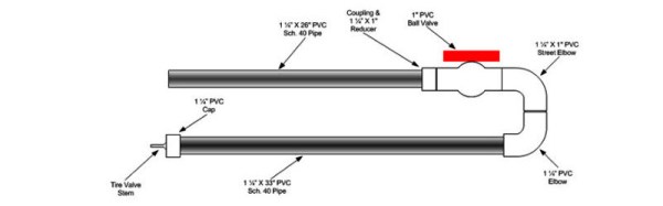
[WB5CXC] has an interesting solution to this problem, at least as far as the application of throwing antenna wires over tall obstacles. He’s made a spud gun from PVC pipe, powered by compressed air. It takes the form of a U-shaped tube with one side of the U being a pressure vessel separated from the other by a ball valve.. Place a close-fitting puck with your wire attached in the open side with the valve closed, pump the pressure vessel full of air with a bicycle pump, and open the valve to send both puck and wire skywards. He says it will clear 100′ trees, counsels the user not to go higher than 100psi, and warns that the speeding puck can be dangerous. We like it already.

We’ve covered many spud guns here at Hackaday in the past, but it seems this is the first wire launching one. We’ve had a steam one for example, or this bolt-action spud gun, but pride of place has to go to the spud gun to end all spud guns.

Via DXZone.

Crowdfunding: A Wireless Oscilloscope

One of the most ingenious developments in test and measuring tools over the last few years is the Mooshimeter. That’s a wireless, two-channel multimeter that can measure voltage and current simultaneously. If you’ve ever wanted to look at the voltage drop and power output on a souped up electrified go-kart, the Mooshimeter is the tool for you.

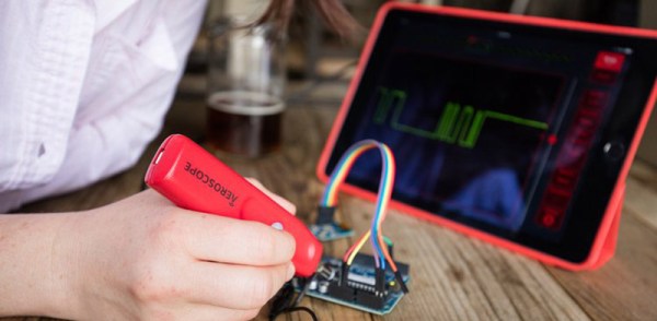
A cheap, wireless multimeter was only the fevered dream of a madman a decade ago. We didn’t have smartphones with Bluetooth back then, so any remote display would cost much more than the multimeter itself. Now this test and measurement over Bluetooth is bleeding over into the rest of the electronics workbench with the Aeroscope,  a wireless Bluetooth oscilloscope.

[Alexander] and [Jonathan], the devs for the Aeroscope got the idea for this device while debugging a mobile robot. The robot would work on the bench, but in the field the problem would reappear. The idea for a wireless troubleshooting tool was born out of necessity.

The specs for the Aeroscope are about equal to the quite capable ‘My First Oscilloscope’ Rigol DS1052E. Analog bandwidth is 100MHz, sample rate is 500 Msamples/second, and the memory depth is 10k points. Resolution per division is 20mV to 10V, and the Aeroscope “Deluxe Package” that includes a few leads, tip, clip, USB cable, and case is about the same price as the Rigol 1052E. The difference, of course, is that the Aeroscope is a single channel, and wireless. That’s fairly impressive for two guys who aren’t a team of Rigol engineers.

As is the case with all Bluetooth test and measurement devices, the proof is in the app. Right now, the Aeroscope only supports iOS 9 devices, but according to the crowdfunding campaign, Android support is coming. Since the device is Open Source, you can always bang something out in Python if you really need to.

While this is a crowdfunding campaign, it’s hosted on Crowd Supply. Crowd Supply isn’t Indiegogo or Kickstarter; there are people at Crowd Supply vetting projects. The campaign still has a month to go, but the first few pledges are putting the Aeroscope right on track to a successful campaign.