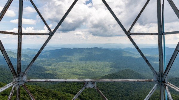
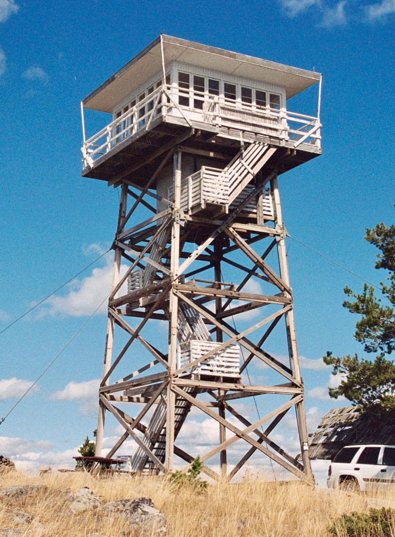
Multi-Board Solder Stencils Explained

There was a time when reflow soldering was an impossibly exotic process at our level, something that only the most superhuman of hackers could even dream of attempting. But a demystification of the process plus the ready availability of affordable PCB and stencil manufacture has rendered into the range of almost all constructors, and it is likely that many of you reading this will have done it yourself.

Screen-printing solder paste onto a single board presents a mild alignment challenge, but how about doing it with many boards at once? [Eric Gunnerson] had this problem with a small-volume board he’s selling, and not being in the happy position of having his PCBs supplied on a panel, had to create his own multi-board alignment jig and stencil. His write-up provides a comprehensive and fascinating introduction to the process whether you are an occasional dabbler or embarking on a production run as he is.

The problem facing any would-be stenciler is that the board has to be held in place reliably in the same alignment as the stencil. With a single board, it’s easy enough to do the usual thing of taping scraps of PCB board to constrain its edges and hold it in place as a rudimentary jig, then lower the stencil onto it. Perhaps you’ve used one of those commercial stencil jigs, in which a set of magnets hold the stencil in place, or maybe you use pins to line everything up.

[Eric] takes us through the process of creating a laser-cut alignment jig for twelve boards, and cutting a matching twelve-board stencil. This includes all the software side using Inkscape, the selection of materials to match PCB thickness, and some of the issues with cutting Mylar sheet for the stencil without shrinkage at the corners. He’s using pins for alignment, and he even finds a handy supply of those in the form of shelf support pins.

We’ve visited the world of reflowing many times before. If you’d like a primer, here’s our Tools of the Trade piece on it, and if you aren’t daunted by larger projects, here’s an account of a prototype run of a significantly complex board.

Dollar Store PCB Holder System

As you get into electronic fabrication and repair, one of the first things you realize is how hard it can be to hold a PCB still while you work on it. Securing them is difficult due to their very nature: they’re often weird shapes, quite fragile, and of course need to be electrically isolated. If you don’t mind spending the money, and have the time to wait on it getting delivered, you can order some nice purpose-built systems for holding PCBs online. But what if you need something fast and cheap?

[Paul Bryson] might have the solution for you. On his blog he’s documented how a trip to the dollar store and some parts from the junk bin allowed him to create a practical system for holding multiple PCBs of various shapes and sizes. The most exotic element of the build here are the hexagonal standoffs; and if you haven’t already salvaged a bunch of those from a curbside computer, he even gives the Mouser link where you can buy them new for a few cents each.

Each individual stanchion of the system is made up of a 3/4″ round magnet with a hex standoff glued to the top. Over the standoff, [Paul] slipped a rubber grommet which gives a nice non-conductive slot to put the edge of the PCB in. Otherwise, a second hex standoff screwed into the first can be used to clamp down on the board. Adjusting the height is as simple as adding a couple more magnets to the stack.

Of course, magnets need something metal to stick on. For that, [Paul] purchased some steel pie pans and matching rack from the dollar store. The round pans are easy to handle and give him plenty of surface area, and the rack makes for an exceptionally convenient storage unit for all the components. The conductivity of the pans might be a concern, but nothing the application of a rubberized spray coating couldn’t fix.

We’ve covered similar systems before, but this one certainly looks to take the top spot in terms of economics. The only thing that would be cheaper would be a few feet of PLA filament and a rubber band.

How To Design Custom Shaped Boards In Fritzing

If you’re looking to get started in designing a few PCBs, you could use one of the many software packages that allow you to create a PCB quickly, easily, and with a minimum amount of fuss. You could also use Fritzing.

Fritzing is terribad and you shouldn’t use it, but that doesn’t mean you still can’t abuse Fritzing to make it do what you want. [Arduino Enigma] recently posted a tutorial on how to design custom PCB shapes for Fritzing. Yes, Fritzing is no longer limited to rectangular PCBs with sharp corners. You can make PCBs in any shape with Fritzing, provided you spend a few hours futzing about with Inkscape.

The goal for this project was to create a rectangular board without any sharp corners for [Arduino Enigma]’s Sinclair Scientific Calculator Emulator. Fritzing can make a board in the shape of a rectangle, in fact, that’s all it can do, but [Arduino Enigma] wanted a rectangle with radiused corners. After hours of work, we have the writeup on how to do it.

The imported board, with 3mm radiused corners.

The process to create a custom-shaped board, in this case, a rectangle with a 3mm radius on the corners, is simple. First, draw a rectangle of the desired shape, then draw even more rectangles as a sublayer of the current layer. Fritzing requires the layer ID to be named ‘board’, ‘silkscreen’ and ‘silkscreen0’, but this cannot be changed in Inkscape itself — you’ll need to edit the file with a text editor. After creating three layers, each containing the shape you want, simply trim the size of the page to the size of the board. Save the file, edit the file in a text editor, and click save. Launch Fritzing, load an image file, and select the SVG you’ve been working on. In just twenty or thirty quick steps, you too can import any shape you can imagine into Fritzing.

There is one pain point to this process. Editing the layer name manually with a text editor pushes this Fritzing hack from a baroque workaround into something that makes us all question the state of Open Source standards. Unfortunately, this is required because Inkscape does not use layer names as the ID in an SVG file. No, it doesn’t make sense, but that’s just the way it is.

For any other PCB design tool, creating a custom-shaped board is simply a matter of drawing a few lines. Fritzing is different, though. The top copper layer is represented as orange, and the bottom copper layer is yellow, a UI decision that doesn’t make sense, even if you aren’t colorblind. Putting more than two layers of copper on a Fritzing board is impossible. Fritzing is a tool you should avoid for PCB layout. That said, [Arduino Enigma] figured out how to do something in Fritzing that you’re not supposed to be able to do and that’s pretty cool.

Simple Jig Uses Electromagnet For Clean Angle Grinder Cuts

We like it when hacks are literal hack jobs, put together with what’s on hand to do a specific job. This quick and dirty angle grinder circle cutter certainly fills the bill, and makes decent cuts in sheet metal to boot.

The build starts with an unlikely source for parts – an old automotive AC compressor. The one that [Made in Poland] chose to sacrifice was particularly nasty and greasy, but after popping off the pulley, the treasure within was revealed: the large, ring-shaped clutch electromagnet. Liberated from the compressor, the electromagnet was attached to a small frame holding a pillow block. That acts as an axis for an adjustable-length arm, the other end of which holds a modified angle grinder. In use, the electromagnet is powered up by a small 12-volt power supply, fixing the jig in place on the stock. The angle grinder is traced around and makes a surprisingly clean cut. Check out the build and the tool in use in the video below.

At the time [Made in Poland] recorded the video, he noted that he did not have a plasma cutter. That appears to have changed lately, so perhaps he’ll swap out the angle grinder for plasma. And maybe he’ll motorize it for even smoother cuts.

Continue reading “Simple Jig Uses Electromagnet For Clean Angle Grinder Cuts”

Wireless SMD microscope ring light

Wireless Ring Light For SMD Microscope

When [Felix Rusu], maker of the popular Moteino boards which started life as wireless Arduino compatibles, says he’s made a wireless ring light for his SMD microscope, we redirect our keystrokes to have a look. Of course, it’s a bit of wordplay on his part. What he’s done is made a new ring light which uses a battery instead of having annoying wires go to a wall wart. That’s important for someone who spends so much time hunched over the microscope. Oh, and he’s built the ring light on a rather nice looking SMD board.

The board offers a few power configurations. Normally he powers it from a 1650 mAh LiPo battery attached to the rear of his microscope. The battery can be charged using USB or through a DC jack for which there’s a place on the board, though he hasn’t soldered one on yet. In a pinch, he can instead power the light from the USB or the DC jack, but so far he’s getting over 6 hours on a single charge, good enough for an SMD session.

The video below shows his SMD board manufacturing process, from drawing up the board in Eagle, laser cutting holes for a stencil, pasting, populating the board, and doing the reflow, along with all sorts of tips along the way. Check it out, it makes for enjoyable viewing.

Here’s another microscope ring light with selectable lighting patterns for getting rid of those pesky shadows. What features would make your SMD sessions go a little easier?

Continue reading “Wireless Ring Light For SMD Microscope”

Box Joint Jig Does Barcodes

Woodworking is the fine art of turning dead tree carcasses into precision instruments. That means breaking out the saws and chisels and making many, many precise cuts over and over. If you have a table saw, every problem becomes a piece of wood, or something like that, and we’ve seen some fantastic jigs that make these precision cuts even easier. We’ve never seen something like this, though. It’s a box joint jig for a table saw, it’s automated, and it puts barcodes on boxes.

[Ben] built this box joint jig a few years ago as a computer-controlled device that slowly advances a piece of wood on a sled, allowing him to create precise, programmable box joints. The design is heavily influenced from [Matthias Wandel]’s screw advance box joint jig, but instead of wood gears (heh), [Ben] is using the Internet of Things. Or a Raspberry Pi, stepper motor, and a few LEDs. Same difference.

Although [Ben]’s previous box joints were all the same size, a programmable box joint jig can do some weird-looking joints. That’s where [Ben] got the idea to encode a barcode in walnut. After using a web app to create a barcode that encodes the number 255 — this is important for later — [Ben] programmed his jig to cut a few slots.

The box was finished as you would expect, but there’s a neat addition to the top. It’s a combination lock that opens when the combination is set to 255. It’s brilliant, and something that could be done with some handsaws and chisels, but this jig makes it so easy it’s hard to think the jig wasn’t explicitly designed for this project.

Move Aside Mercury: Measuring Temperature Accurately With An RTD

Temperature is one of the most frequently measured physical quantities, and features prominently in many of our projects, from weather stations to 3D printers. Most commonly we’ll see thermistors, thermocouples, infrared sensors, or a dedicated IC used to measure temperature. It’s even possible to use only an ordinary diode, leading to some interesting techniques.

Often we only need to know the temperature within a degree Celsius or two, and any of these tools are fine. Until fairly recently, when we needed to know the temperature precisely, reliably, and over a wide range we used mercury thermometers. The devices themselves were marvels of instrumentation, but mercury is a hazardous substance, and since 2011 NIST will no longer calibrate mercury thermometers.

A typical Pt100 RTD probe

Luckily, resistance temperature detectors (RTDs) are an excellent alternative. These usually consist of very thin wires of pure platinum, and are identified by their resistance at 0 °C. For example, a Pt100 RTD has a resistance of 100 Ω at 0 °C.

An accuracy of +/- 0.15 °C at 0 °C is typical, but accuracies down to +/- 0.03 °C are available. The functional temperature range is typically quite high, with -70 °C to 200 °C being common, with some specialized probes working well over 900 °C.

It’s not uncommon for the lead wires on these probes to be a meter or more in length, and this can be a significant source of error. To account for this, you will see that RTD probes are sold in two, three, and four wire configurations. Two-wire configurations do not account for lead wire resistance, three-wire probes account for lead resistance but assume all lead wires have the same resistance, and four-wire configurations are most effective at eliminating this error.

In this article we’ll be using a 3-wire probe as it’s a good balance between cost, space, and accuracy. I found this detailed treatment of the differences between probe types useful in making this decision.

Continue reading “Move Aside Mercury: Measuring Temperature Accurately With An RTD”