Like many mobile gamers, [Daniel] has found himself caught up by the addictive “White Tiles” game. Rather than play the game himself though, [Daniel] decided to write his own automatic White Tiles player. While this hack has been pulled off before, it’s never been well documented. [Daniel] used knowledge he gleaned on Hackaday and Hackaday.io to achieve his hack.
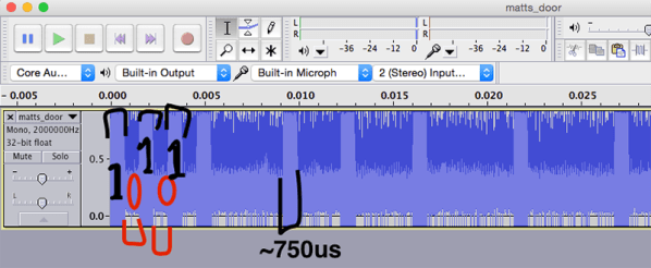
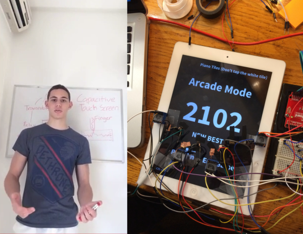
The basic problem is sensing white vs black tiles and activating the iPad’s capacitive touch screen. On the sensing end, [Daniel] could have used phototransistors, but it turned out that simple CdS cells, or photoresistors, were fast enough in this application. Activating the screen proved to be a bit harder. [Daniel] initially tried copper tape tied to transistors, but found they wouldn’t reliably trigger the screen. He switched over to relays, and that worked perfectly. We’re guessing that changing the wire length causes enough of a capacitance change to cause the screen to detect a touch.
The final result is a huge success, as [Daniel’s] Arduino-based player tears through the classic game in only 3.9 seconds! Nice work [Daniel]!
Click past the break to see [Daniel’s] device at work, and to see a video of him explaining his creation.
Continue reading “Arduino Plays White Tiles On Your Mobile Touchscreen”