At the heart of many amateur radio and other projects lies the VFO, or Variable Frequency Oscillator. Decades ago this would have been a free-running LC tuned circuit, then as technology advanced it was replaced by a digital phase-locked-loop frequency synthesiser and most recently a DDS, or Direct Digital Synthesis chip in which the waveform is produced directly by a DAC. The phase-locked loop (PLL) remains a popular choice due to ICs such as the Si5351 but is rarely constructed from individual chips as it once might have been. [fvfilippetti] has revisited this classic circuit by replacing some of its complexity with an Arduino (Spanish language, Google Translate link).
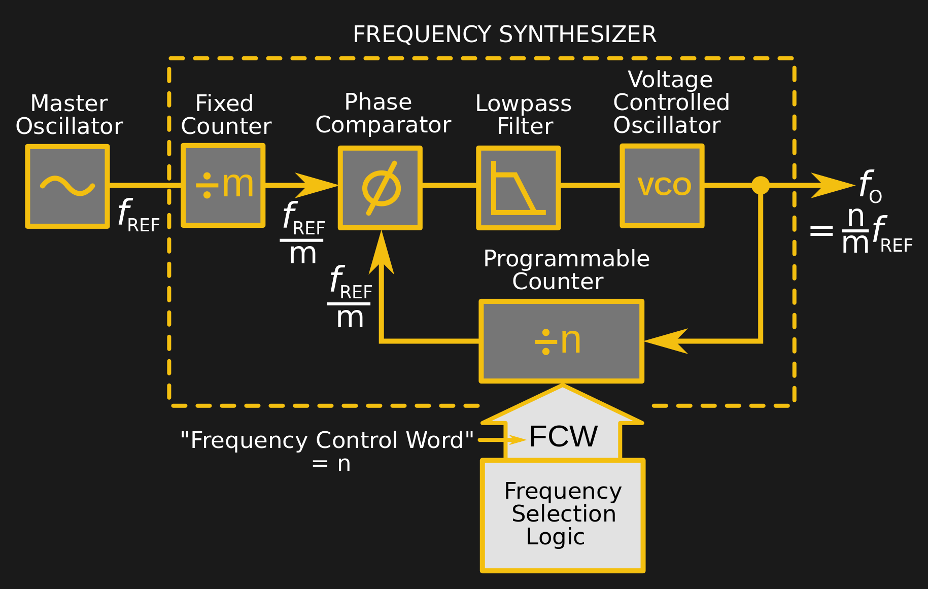
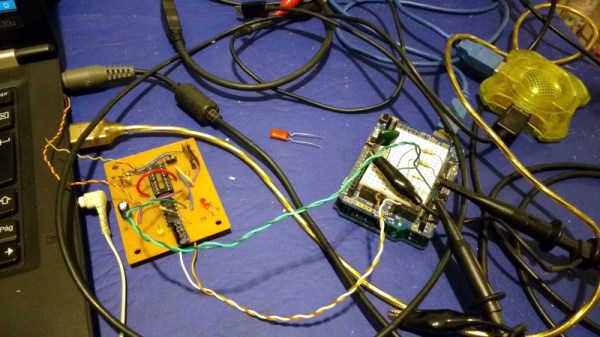
A PLL is a simple circuit in which one oscillator is locked to another by controlling it with a voltage derived from comparing the phase of the two. Combining a PLL with a set of frequency dividers creates a frequency synthesiser, in which a variable frequency oscillator can be locked to a single frequency crystal with the output frequency set by the division ratios. The classic PLL chip is the CMOS 4046 which would have been combined with a pile of logic chips to make a frequency synthesiser. The Arduino version uses the Arduino’s internal peripherals to take the place of crystal oscillator, dividers, and phase comparator, resulting in an extremely simple physical circuit of little more than an Arduino and a VCO for the 40 metre amateur band. The code can be found on GitLab, should you wish to try for yourself.
It would be interesting to see how good this synthesiser is at maintaining both a steady frequency and minimal phase noise. It’s tempting to think of such things as frequency synthesisers as a done deal, so it’s always welcome to see somebody bringing something new to them. Meanwhile if PLLs are new to you, we have just the introduction for you.
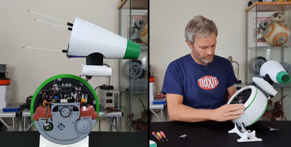
 D-O is effectively a two-wheeled self-balancing robot, with two thin drive wheels on the outer edges of the main body. A wide flexible tire covers the space between the two wheels, where the electronics are housed, without actually forming part of the drive mechanism. The main drive motors are a pair of geared DC motors with encoders to allow closed-loop control down to very slow speeds. The brains of the operation is an Arduino MKR-W1010 GET on a stack that consists of a motor driver, shield, IMU shields, and prototyping shield. [Matt] did discover a design error on the motor driver board, which caused the main power switching MOSFET to burst into flames from excessive gate voltage. Fortunately he was able to work around this by simply removing the blown MOSFET and bridging the connection with a wire.