Hard Drive Gives Its Life To Cool 3D Prints

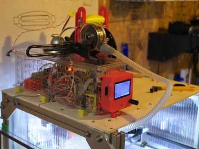
[Mark Rehorst] has been on the hunt for the perfect 3D printer cooling fan and his latest take is a really interesting design. He’s printed an impeller and housing, completing the fan using a hard drive motor to make it spin.

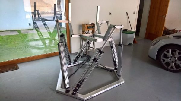
We should take a step back to see where this all began. Many 3D printers us a cooling fan right at the tip of the extruder because the faster you faster you cool the extruded filament, the fewer problems you’ll have with drooping and warping. Often this is done with a small brushless fan mounted right on the print head. But that adds mass to the moving head, contributing to problems like overshoot and oscillation, especially on larger format printers that have longer gantries. [Mark] just happens to have an enormous printer we covered back in January and that’s the machine this fan targets.

CPAP fan and duct tubing

Make sure you give [Mark’s] Mother of all print cooling fans article a look. His plan is to move the fan off of the print head and route a flexible tube instead. He tried a couple of fans, settling on one he pulled from a CPAP machine (yes the thing you wear at night to combat sleep apnea) found in the parts bin at Milwaukee Makerspace. It works great, moving quite a bit more air than necessary. The problem is these CPAP parts aren’t necessarily easy to source.

You know what is easy to source? Old hard drives. [Mark] mentions you likely have one sitting around and if not, your friends do. We have to agree with him. Assuming you already have a 3D printer (why else do you want to print this fan?), the only rare part in this mix is the ESC to make the motor spin. Turns out we just saw a BLDC driver build that would do the trick. But in [Mark’s] case he found a rather affordable driver that suits his needs which is used in the video demo below.

Continue reading “Hard Drive Gives Its Life To Cool 3D Prints”

Completely Scratch-Built Electronic Speed Controller

Driving a brushless motor requires a particular sequence. For the best result, you need to close the loop so your circuit can apply the right sequence at the right time. You can figure out the timing using a somewhat complex circuit and monitoring the electrical behavior of the motor coils. Or you can use sensors to detect the motor’s position. Many motors have the sensors built in and [Electronoobs] shows how to drive one of these motors in a recent video that you can watch below. If you want to know about using the motor’s coils as sensors, he did a video on that topic, earlier.

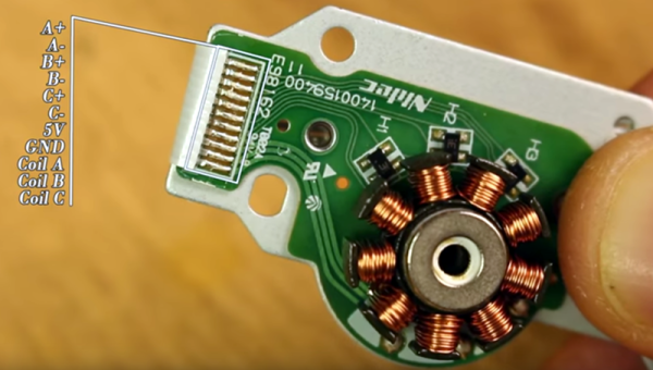
The motor in question was pulled from an optical drive and has three hall effect sensors onboard. Having these sensors simplifies the drive electronics considerably.

Continue reading “Completely Scratch-Built Electronic Speed Controller”

A Brushless Motor On A PCB, Made From PCB

At Hackaday, we really appreciate it when new projects build on projects we’ve featured in the past. It’s great to be able to track back and see what inspires people to pick up someone else’s work and bring it to the next level or take it down a totally new path.

This PCB brushless motor is a great example of the soft collaboration that makes the Hackaday community so powerful. [bobricius] says he was inspired by this tiny PCB BLDC when he came up with his design. His write-up is still sparse at this point, but it looks like his motor is going to be used to drive a small robot. As with his inspiration, this motor has the stator coils etched right into the base PCB. But there are some significant improvements, like increasing the stator coil count from six to eight, as well as increasing the overall size of the motor. [bobricius] has also done away with the 3D-printed rotor of the original, opting to fabricate his rotor from stacked PCBs with cutouts for 5-mm neodymium magnets. We like the idea of using the same material throughout the motor, and it also raises the potential for stacking a second stator on the other side of the rotor, which might help mechanically and electrically. Even still, the prototype seems to hold its own in the video below.

This is [bobricius]’ second entry in the 2018 Hackaday Prize so far, after his not-a-Nixie tube display. Have you entered anything yet? Get to it! Prizes, achievements, and glory await.

Continue reading “A Brushless Motor On A PCB, Made From PCB”

IQ Makes Smarter Motors

We think of motors typically as pretty dumb devices. Depending on the kind, you send them some current or some pulses, and they turn. No problem. Even an RC servo, which has some smarts on board, doesn’t have a lot of capability. However, there is a new generation of smart motors out that combine the mechanical motor mechanism with a built-in controller. [Bunnie] looks at one that isn’t even called a motor. It is the IQ position module.

Despite the name, these devices are just a brushless DC motor (BLDC) with a controller and an API. There’s no gearing, so backdriving the motor is permissible and it can even double as a motion sensor. The video below shows [Bunnie] making one module track the other using just a little bit of code.

Continue reading “IQ Makes Smarter Motors”

Here’s Why Hoverboard Motors Might Belong In Robots

[madcowswe] starts by pointing out that the entire premise of ODrive (an open-source brushless motor driver board) is to make use of inexpensive brushless motors in industrial-type applications. This usually means using hobby electric aircraft motors, but robotic applications sometimes need more torque than those motors can provide. Adding a gearbox is one option, but there is another: so-called “hoverboard” motors are common and offer a frankly outstanding torque-to-price ratio.

A teardown showed that the necessary mechanical and electrical interfacing look to be worth a try, so prototyping has begun. These motors are really designed for spinning a tire on the ground instead of driving other loads, but [madcowswe] believes that by adding an encoder and the right fixtures, these motors could form the basis of an excellent robot arm. The ODrive project was a contender for the 2016 Hackaday Prize and we can’t wait to see where this ends up.

This Tiny Motor Is Built Into A PCB

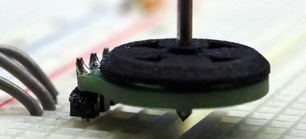
Mounting a motor on a PCB is nothing new, right? But how about making the PCB itself part of the motor? That’s what [Carl Bugeja] has done with his brushless DC motor in a PCB project, and we think it’s pretty cool.

Details on [Carl]’s Hackaday.io page are a bit sparse at this point, but we’ve been in contact with him and he filled us in a little. The PCB contains the stator of the BLDC and acts as a mechanical support for the rotor’s bearing. There are six spiral coils etched into the PCB, each with about 40 turns. The coils are distributed around the axis; connected in a wye configuration, they drive a 3D-printed rotor that has four magnets pressed into it. You can see a brief test in the video below; it seems to suffer from a little axial wobble due to the single bearing, but that could be handled with a hat board supporting an upper bearing.

We see a lot of potential in this design. [Carl] mentions that the lack of cores in the coil limit it to low-torque applications, but it seems feasible to bore out the center of the coils and press-fit a ferrite slug. Adding SMD Hall sensors to the board for feedback would be feasible, too — in fact, an entire ESC and motor on one PCB could be possible as well. [Carl] has promised to keep the project page updated, and we’re looking forward to more on this one.

For a more traditional approach to printed motors, check out this giant 3D-printed BLDC.

Continue reading “This Tiny Motor Is Built Into A PCB”

Scrap A Hard Drive, Build A Rotary Encoder

There’s something to be said for the feel of controls. Whether it’s the satisfying snap of a high-quality switch or the buttery touch of the pots on an expensive amplifier, the tactile experience of the controls you interact with says a lot about a device.

[GreatScott!] knows this, and rather than put up with the bump and grind of a cheap rotary encoder, he decided to find an alternative. He ended up exploring hard drive motors as encoders, and while the results aren’t exactly high resolution, he may be onto something. Starting with a teardown of some old HDDs — save those magnets! — [Scott!] found that the motors fell into either the four-lead or three-lead categories. Knowing that HDD motors are brushless DC motors, he reasoned that the four-lead motors had their three windings in Wye configuration with the neutral point brought out to an external connection. A little oscilloscope work showed the expected three-phase output when the motor hub was turned, with the leading and lagging phases changing as the direction of rotation was switched. Hooked to an Arduino, the motor made a workable encoder, later improved by sending each phase through a comparator and using digital inputs rather than using the Nano’s ADCs.

It looks like [GreatScott!]’s current setup only responds to a full rotation of the makeshift encoder, but we’d bet resolution could be improved. Perhaps this previous post on turning BLDC motors into encoders will help.

Continue reading “Scrap A Hard Drive, Build A Rotary Encoder”