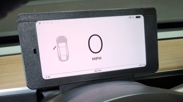
The Tesla Model 3 and Model Y are popular electric vehicles that dispense with some of the usual provisions you’d expect in a typical car. Namely, there’s no dash cluster in front of the driver; instead, all information is solely displayed on the center console screen. [Nick Nguyen] wasn’t a fan of this setup, and decided to hack together a dash cluster of his own.
The CANdash works in a simple fashion, snooping the Tesla’s CAN bus for all the information relevant to the vehicle’s operation. It’s capable of displaying everything from speed to the remaining range in the battery, while also allowing the user to keep an eye on things like coolant temperatures and whether the Tesla Autopilot system is currently available.
The build relies on a CANserver, an ESP32-based device specifically built for hooking up to the CAN bus on Tesla vehicles and sharing the data externally. The data can then be piped wirelessly to an Android phone running CANdash to display all the desired information. With the help of an aftermarket dash clip or a 3D printed custom mount, the phone can then be placed behind the steering wheel to display data in the usual location.
It’s a simple, straightforward hack that gives Tesla owners a useful feature that they’re otherwise missing from the factory. The US automakers cars are proving to be fertile ground for hackers and DIYers, with one man recently saving thousands on a battery swap with a simple mod. Video after the break.
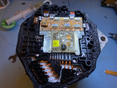
Nice thermal design, but conformal coating and no ID marks make this tough to reverse engineer
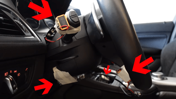
[Willem Melching] owns a 2010 Volkswagen Golf – a very common vehicle in Europe – and noticed that whilst the electronic steering rack supports the usual Lane Keep Assist (LKAS) system, and would be theoretically capable of operating in a far more advanced configuration using openpilot, there were some shortcomings in VW’s implementation which means that it would not function for long enough to make it viable. Being very interested in and clearly extremely capable at reverse engineering car ECUs and hacking them into submission, [Willem] set about documenting his journey to unlocking openpilot support for his own vehicle.
And what a journey it was! The four-part blog series is beautifully written, showing every gory detail and all tools used along the way. The first part shows the Electronic Power Steering (EPS) ECU from a 2010 Volkswagen Golf Mk6 module (which rides on the back of the three-phase steering rack motor) being cracked open to reveal an interesting multi-chip module approach, with bare die directly bonded to a pair of substrate PCBs, that are in turn, bonded to the back of the motor casing, presumably for heat dissipation reasons. Clever design, but frustrating at the same time as this makes part identification somewhat tricker!
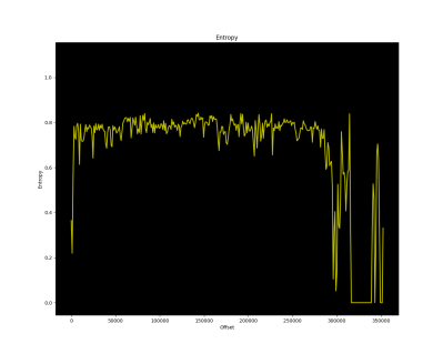
Entropy less the 1.0, and zero sections indicate no encryption applied
[Willem] uses a variety of tools and tricks to power up and sniff the ECU traffic on the CAN bus, when hooked up to a SAE J2534-compliant debug tool, eventually determining it speaks the VW-specific TP2.0 CAN bus protocol, and managed to grab enough traffic to check that it was possible to use the standard KWP2000 diagnostic protocol to access some interesting data. Next was a very deep dive into reverse engineering update images found online, by first making some trivial XOR operations, then looking at an entropy plot of the file using Binwalk to determine if he really did have code, and if it was encrypted or not, After running cpu_rec, it was determined the CPU was a Renesas V850. Then the real work started – loading the image into Ghidra to start making some guesses of the architecture of the code, to work out what needed patching to make the desired changes. In the final part of the series, [Willem] extracts and uses the bootloader procedure to partially patch the code configuration area of his vehicle and unlocks the goal he was aiming at – remote control of his steering. (OK, the real goal was running openpilot.)
In our opinion, this is a very interesting, if long, read showing a fascinating subject expertly executed. But we do want to stress, that the vehicular EPS module is an ASIL-D safety tested device, so any hacks you do to a road-going vehicle will most definitely void your insurance (not to mention your warranty) if discovered in the event of a claim.
Something like 99% of the people on the road at any given moment will consider themselves an above-average driver, something that’s as statistically impossible as it is easily disproven by casual observation. Drivers make all kinds of mistakes, but perhaps none as annoying and avoidable as failure to use their turn signal. This turn signal monitor aims to fix that, through the judicious use of negative feedback.
Apparently, [Mark Radinovic] feels that he has a predisposition against using his turn signal due to the fact that he drives a BMW. To break him of that habit, one that cost him his first BMW, he attached Arduino Nano 33 BLEs to the steering wheel and the turn signal stalk. The IMUs sense the position of each and send that over Bluetooth to an Arduino Uno WiFi. That in turn talks over USB to a Raspberry Pi, which connects to the car’s stereo via Bluetooth to blare an alarm when the steering wheel is turned but the turn signal remains untouched. The video below shows it in use; while it clearly works, there are a lot of situations where it triggers even though a turn signal isn’t really called for — going around a roundabout, for example, or navigating a sinuous approach to a drive-through window.
While [Mark] clearly built this tongue firmly planted in cheek, we can’t help but think there’s a better way — sniffing the car’s CANbus to determine steering angle and turn signal status comes to mind. This great workshop on CANbus sniffing from last year’s Remoticon would be a great place to start if you’d like a more streamlined solution than [Mark]’s.
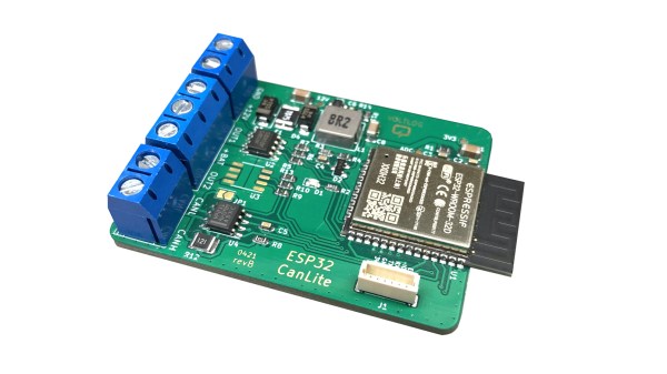
[Voltlog] has been hacking away at the CAN bus console of his VW Golf for quite some time now. Presumably, for his projects, the available CAN bus interface boards are lacking in some ways, either technically and/or price. So [Voltlog] designed his own wireless CAN bus hacking and development module called the ESP32 CanLite (see the video below the break). The board was tailored to meet the needs of his project and he claims it is not a universal tool. Nevertheless we think many folks will find the features he selected for this module will be a good fit for their projects as well.
In his introduction of the design, he walks through the various design decisions he faced. As the project name suggests, he’s using the ESP32 as the main controller due to it’s wireless radios and built-in CAN controller. The board is powered from the car’s +12V power, so it uses a wide input range ( 4 to 40 V ) switching regulator. One feature he added was the ability to switch automotive accessories using the ST VN750PC, a nifty high-side driver in an SO-8 package with integrated safety provisions.
The project is published as open source and the files can be pulled from his GitHub repository. We noticed the debug connector labeled VOLTLINK on the schematic, and found his description of this custom interface interesting. Basically, he was not satisfied with the quality and performance of the various USB-to-serial adapters on the market and decided to make his own. Could this be a common theme among [Voltlog]’s projects?
A word of warning if you want to build the ESP32 CanLite yourself. While [Voltlog] had intentionally selected parts that were common and easy to purchase when the project began, several key chips have since become nearly impossible to obtain these days due to the global parts shortage issue (it’s even out of stock on his Tindie page).
If you want to dig deeper into CAN bus hacking, check out this talk that we wrote about back in 2016. Do you have any favorite CAN bus development boards and/or tools? Let us know in the comments below.
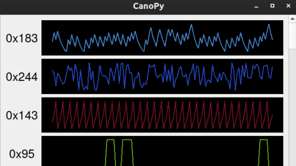
As cars have become more sophisticated electronically, understanding the CAN bus that forms the backbone of automotive digital systems has become more and more important for hacking cars. Inexpensive microcontroller CAN interfaces have made obtaining the raw CAN bus traffic trivial, but interpreting that traffic can be pretty challenging. In order to more easily visualize CAN traffic, [TJ Bruno] has developed CanoPy, a Python tool for visualizing CAN messages in real time.
A basic PC CAN interface simply dumps the bus’s message traffic into the terminal, while more sophisticated tools organize messages by the address of their intended recipients. Both of these approaches digitally lift the hood and let you examine what your car is thinking, but the wall-of-numbers approach makes finding the patterns that hold the keys to reverse engineering difficult. Automatically plotting the data with CanoPy makes finding correlations much easier, after which the text-based tools can be used to focus in on a few specific addresses.
We’ve seen several so-called “digital dash” upgrades over the years that either augment, or completely replace, a vehicle’s original dashboard indicators with new displays. Whether its seven segment LEDs or a full-on graphical interface powered by the Raspberry Pi, the end result is the same: a dashboard that looks wildly different than it did when the car rolled off the assembly line.
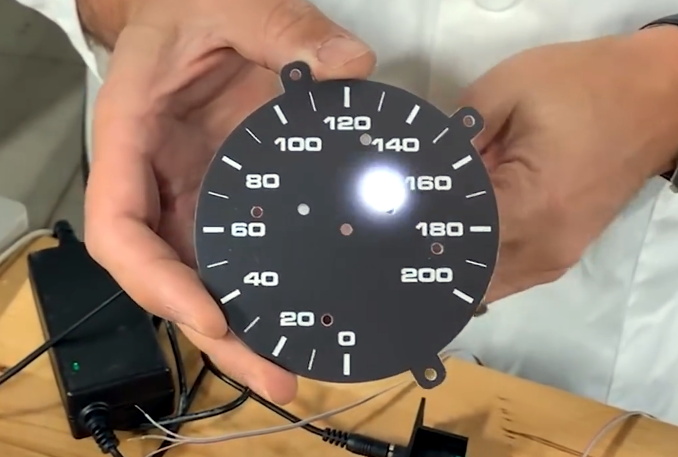
But this LED dashboard project from [Flyin’ Miata] takes a slightly different approach. Rather than replace the analog gauges entirely, rings of RGB LEDs of the same diameter were placed behind their matte black faces. When the LEDs are off you’d never notice them, but once they kick on, the light is clearly visible through the material.
LEDs can easily shine through the gauge face.
So far, it looks like most of the work seems to have been put into the tachometer. The firmware running on the CAN equipped Adafruit Feather M4 can do things such as light up a dynamic redline based on current engine temperature. It will also light up the LEDs to follow the analog gauge as it moves around, which might not have much practical application, but certainly looks cool.
On the speedometer side, the LEDs seem to be used primarily as warning indicators. As demonstrated in the video below, the whole gauge can light up bright red to indicate a critical situation such as low oil pressure. If you wanted to, the system could also be configured with different colors corresponding to various possible fault conditions.
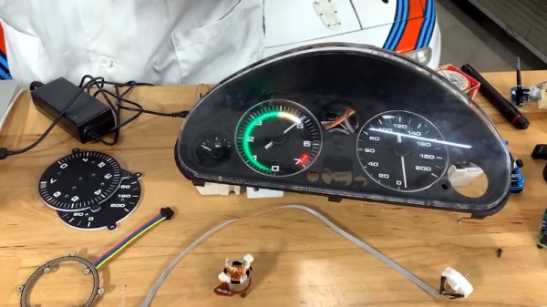
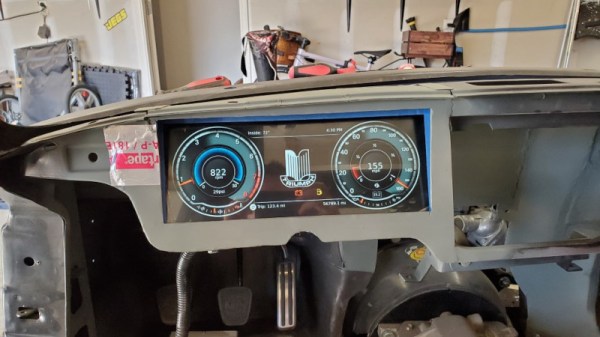
Analog gauges gave way to all manner of fancy electroluminescent and LED gauges in the ’80s, but the trend didn’t last long. It’s only in the last decade or so that LCD digital gauges have really started to take off in premium cars. [Josh] is putting a modern engine and drivetrain into his classic Triumph GT6, and realised that he’d have to scrap the classic mechanical gauge setup. After not falling in love with anything off the shelf, he decided to whip up his own solution from scratch.
The heart of the build is a Raspberry Pi 4, which interfaces with the car’s modern aftermarket ECU via CANBUS thanks to the PiCAN3 add-on board. Analog sensors, such as those for oil pressure and coolant temperature, are interfaced with a Teensy 4.0 microcontroller which has the analog to digital converters necessary to do the job. Display is via a 12.3″ super-wide LCD sourced off Aliexpress, with the graphics generated by custom PixiJS code running in Chromium under X.
The result is comparable with digital displays in many other modern automobiles, speaking to [Josh]’s abilities not just as a programmer but a graphic designer, too. As a bonus, if he gets sick of the design, it’s trivial to change the graphics without having to dig into the car’s actual hardware.