As a new parent, there’s lots you have to do. You have to buy a car seat, get the baby’s room ready, figure out daycare; all the boring but unavoidable minutiae of shepherding a tiny human. But for the more creative types, that list might include warming up the 3D printer or putting a fresh bit in the CNC, as there’s no better way to welcome a little one into the world than giving them some custom gear to get started with.
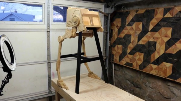
 That’s certainly been the plan for [Matthew Regonini], who’s been showering his son with DIY playthings. He recently wrote in to tell us about his awesome AT-ST high chair build that manages to turn the drudgery of getting a baby to eat into an epic worthy of a John Williams score.
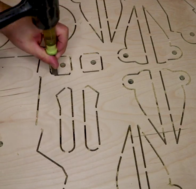
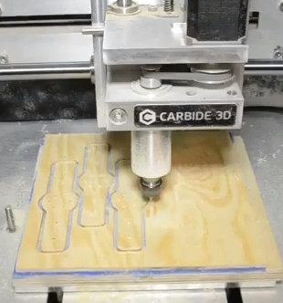
This isn’t the first time [Matthew] has turned dead trees into Imperial hardware. Last year we covered his fantastic AT-AT rocker which utilized the same construction techniques. The parts are cut out of plywood with his CNC, separated, cleaned up on a spindle sander, and finally assembled with wood glue and a few strategic fasteners. The depth and level of detail he’s able to achieve when the individual pieces are stacked up is exceptionally impressive. If builds like these don’t get you thinking about adding a CNC to your workshop, nothing will.
As with the AT-AT, the finish on the high chair is simply a healthy application of polyurethane. This keeps the wood from being porous (important as this build will be seeing its fair share of food and liquids) while retaining a natural look. Some might be tempted to paint it up in appropriate Imperial colors, but that might be a bit imposing considering its intended occupant.
Really, the only downside with this build is how quickly his son will outgrow it. The obvious solution to the problem is a constant supply of fresh babies to pilot it, but that’s one type of creation that we don’t generally detail here on Hackaday. If you have questions, ask your parents.
Incidentally, it’s starting to look like we’ve got a plywood arms-race going on. We’re excited to see somebody take it to the next level. A little scared, but mainly excited.
Continue reading “AT-ST High Chair Elevates Lucky Jedi Youngling”

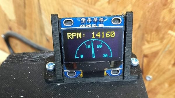
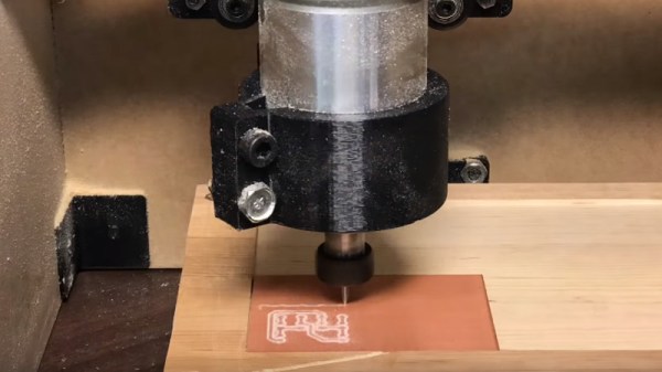
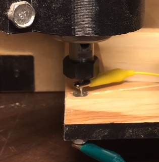
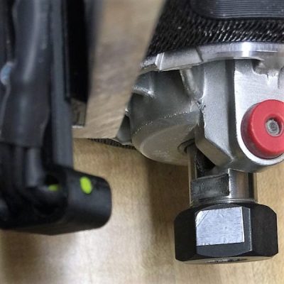 The CNC router in question is the popular Sienci, and the 3D-printed brackets for the photodiode and LED are somewhat specific for that machine. But [tmbarbour] has included STL files in his exhaustively detailed write-up, so modifying them to fit another machine should be easy. The sensor hangs down just far enough to watch a reflector on one of the flats of the collet nut; we’d worry about the reflector surviving tool changes, but it’s just a piece of shiny tape that’s easily replaced. The sensor feeds into a DIO pin on a Nano, and a small OLED display shows a digital readout along with an analog gauge. The display update speed is decent — not too laggy. Impressive build overall, and we like the idea of using a piece of PLA filament as a rivet to hold the diodes into the sensor arm.
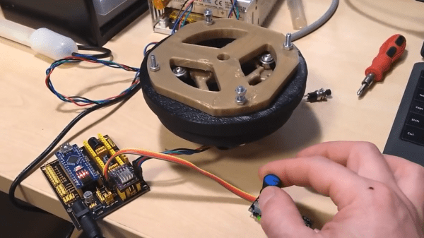
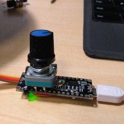 In a project, repetitive tasks that break the flow of development work are incredibly tiresome and even simple automation can make a world of difference. [Simon Merrett] ran into exactly this while testing different stepper motors in a strain-wave gear project. The system that drives the motor accepts G-Code, but he got fed up with the overhead needed just to make a stepper rotate for a bit on demand. His solution? A