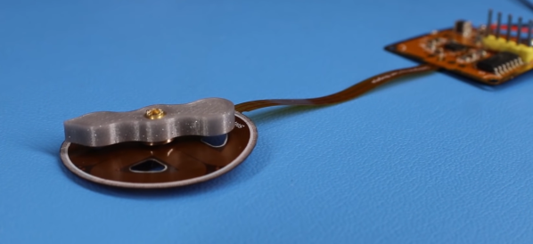
We’ve noticed that [Carl Bugeja] likes flexible PCBs. His latest exploit is to make PCB-based springs that combine with some magnets to create little devices that jump. We aren’t sure what practical use these might have, but they are undeniably novel and you can see them — um — jumping around, in the video, below.
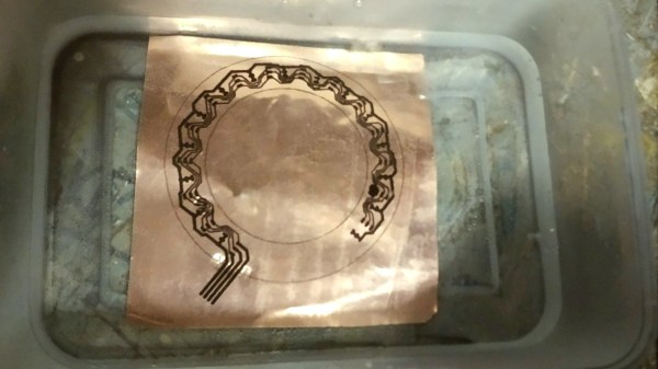
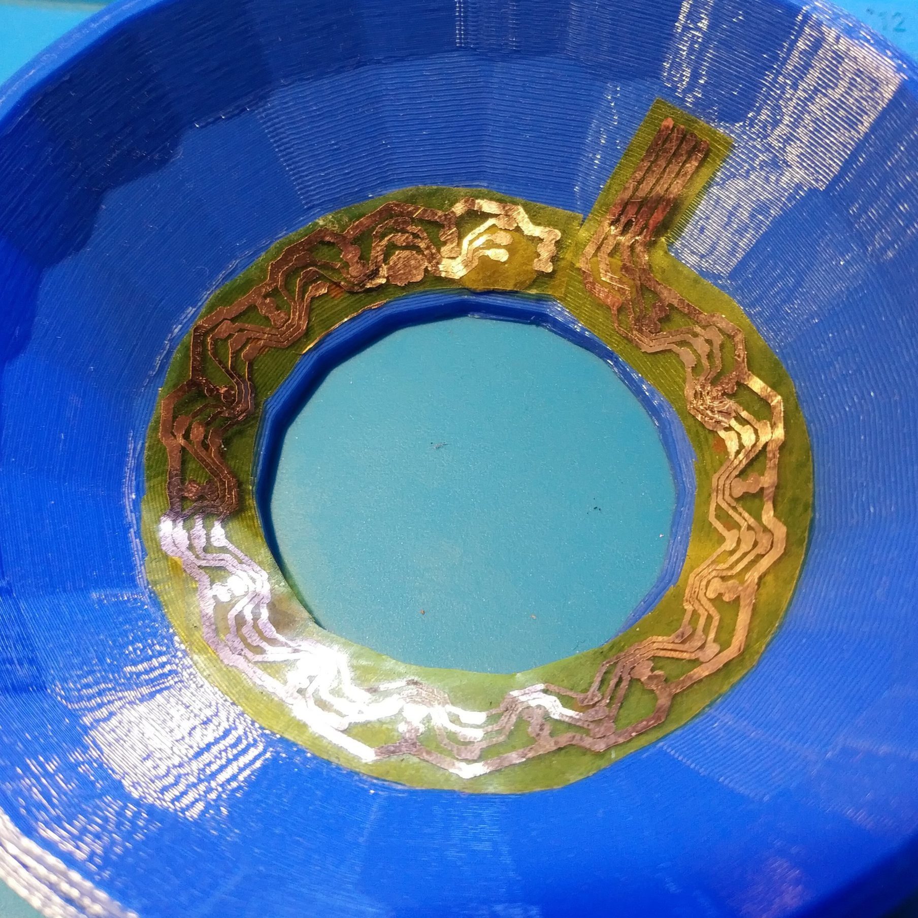
[Carl] did many experiments with the spring construction and design. You can see several of the iterations in the video, not all of which worked out well. A PCB coil in the base becomes magnetized when current flows and this repels or attracts the magnets at the other end of the spring. What can you do with a PCB spring? We aren’t sure. Maybe this is how your next microrobot could climb stairs?
Adding stiffeners produced springs too stiff for the electromagnet to attract. We wondered if a different coil design at the base might be more effective. For that matter, you might not have to use a flat PCB coil in that position if you were really wanting to optimize the jumping behavior.
Usually, when we are checking in with [Carl] he is making PCB-based motors. Or, sometimes, he’s making PCB heaters for reflow soldering. We’ve seen jumping robots, before, of course. we will say the magnets seem less intense than using compressed air.
Continue reading “When [Carl] Says Jump, PCBs Say “How High?””