3D Printed Lens Gears For Pro-grade Focus Pulling

Key Grip, Gaffer, Best Boy – any of us who’ve sat through every last minute of a Marvel movie to get to the post-credits scene – mmm, schawarma! – have seen the obscure titles of folks involved in movie making. But “Focus Puller”? How hard can it be to focus a camera?

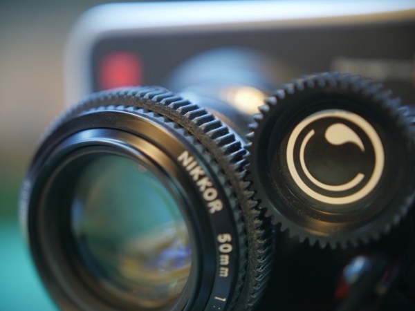
Turns out there’s a lot to the job, and in a many cases it makes sense to mechanize the task. Pro cinematic cameras have geared rings for just that reason, and now your DSLR lens can have them too with customized, 3D printed follow-focus gears.

Gear_Selection_01_full_render_preview_featured
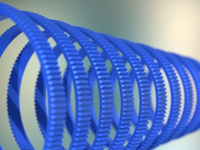
Unwilling to permanently modify his DSLR camera lens and dissatisfied with after-market lens gearing solutions, [Jaymis Loveday] learned enough OpenSCAD to generate gears from 50mm to 100mm in diameter in 0.5mm increments for a snug friction fit. Teamed up with commercially available focus pulling equipment, these lens gears should really help [Jaymis] get professional results from consumer lenses. 

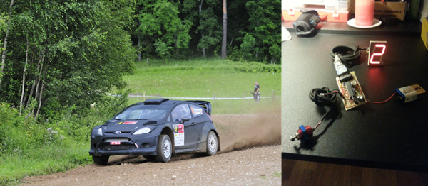
Unfortunately, [Jaymis] doesn’t include any video of the gears in action, but the demo footage shown below presumably has some shots that were enabled by his custom gears. And even if it doesn’t, there are some really cool shots in it worth watching.

And for the budding cinematographers out there without access to a 3D printer, there’s always this hardware store solution to focus pulling.

Continue reading “3D Printed Lens Gears For Pro-grade Focus Pulling”

Hackaday Fail: A $3000 Prototype That Doesn’t Work

[Dan Royer] is hard at work building his own personal robot army. Robots mean motors, and motors mean gearboxes. In [Dan]’s case, gearboxes mean $3000 wasted on a prototype that doesn’t work. Why doesn’t it work? He doesn’t know, and we don’t either.

[Dan] would like to use small but fast DC motors for his robots coupled to a gearbox to step down the speed and increase the torque. The most common way of doing this is with a planetary gear set, but there’s a problem with the design of planetary gears – there is inherent backlash and play between the gears. This makes programming challenging, and the robot imprecise.

A much better way to gear down a small DC motor is a hypocycloid gear. If you’ve ever seen the inside of a Wankel engine, this sort of gearing will look very familiar: a single gear is placed slightly off-axis inside a ring gear. On paper, it works. In reality, not so much.

[Dan] spent $3000 on a prototype hypocycloid gearbox that doesn’t turn without binding or jamming. The gear was made with incredible tolerances and top quality machining, but [Dan] has a very expensive paper weight sitting on his desk right now.

If anyone out there has ever designed or machined a hypocycloid gearbox that works, your input is needed. The brightest minds [Dan] met at the Bring A Hack event at Maker Faire last weekend could only come up with. ‘add more lasers’, but we know there’s a genius machinist out there that knows exactly how to make this work.


2013-09-05-Hackaday-Fail-tips-tileHackaday Fail is a column which runs every now and again. Help keep the fun rolling by writing about your past failures and sending us a link to the story — or sending in links to fail write ups you find in your Internet travels.

Workbench Eye Candy From Around The World

The workbench. We’re always looking for ways to make the most out of the tools we have, planning our next equipment purchase, all the while dealing with the (sometimes limited) space we’re allotted. Well, before you go off and build your perfect electronics lab, this forum thread on the EEVblog should be your first stop for some extended drooling research.

You’ll find a great discussion about everything from workbench height, size, organization, shelf depth, and lighting, with tons of photos to go with it. You’ll also get a chance to peek at how other people have set up their labs. (Warning, the thread is over 1000 posts long, so you might want to go grab a snack.)

We should stop for a moment and give a special note to those of you who are just beginning in electronics. You do not need to have a fancy setup to get started. Most of these well equipped labs is the result of being in the industry for years and years. Trust us when we say, you can get started in electronics with nothing more than your kitchen table, a few tools, and a few parts. All of us started that way. So don’t let anything you see here dissuade you from jumping in. As proof, we’ve seen some amazingly professional work being done with the most bare-bones of tools (and conversely, we seen some head-scratching projects by people with +$10,000 of dollars of equipment on their desk.)

Here’s some links that you might find handy when setting up a lab. [Kenneth Finnegan] has a great blog post on how his lab is equipped. And [Dave Jones] of the EEVblog has a video covering the basics. One of the beautiful things about getting started in electronics is that used and vintage equipment can really stretch your dollars when setting up a lab. So if you’re looking into some vintage gear, head on over to the Emperor of Test Equipment. Of course no thread about workbenches would be complete with out a mention of Jim Williams’ desk. We’ll leave the discussion about workbench cleanliness for the comments.

R/C Wheel Loader Clears Snow, Lifts People

For some people, R/C cars just aren’t enough. [djMedic2008] has gotten his hands on a monstrous 1/5 scale wheel loader. The loader weighs in at 500lbs, and can lift up to 250 lbs. It was built several years ago as a prototype by [Richard] at Tiny Titan Earth Movers.

The design is based upon huge machines made by companies like Caterpillar and Komatsu. The 4WD system is driven a DC motor through a worm gear reduction. Bucket operation and steering are both operated by a hydraulic system driven by an electric pump. Just like the full-scale machines, the mini loader uses an articulated steering system. The front wheels are locked in place while the entire chassis bends at the middle pivot point. This allows for a much stronger solid front axle.

loader-gear
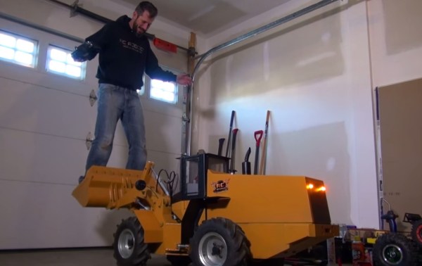
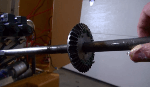
After several years of hard life, the loader came to [djMedic] in need of some TLC. The biggest issue was that the rear axle bevel gear had lost several teeth. This gear is under enormous loads when the loader is turning. A gear made of harder steel was the easy answer. Thankfully, you can order high carbon steel bevel gears from Amazon. The repair video gives us a look at the design of the loader. The main components of the machine are welded up from steel sheet and tube stock. This means that [djMedic] won’t have a hard time finding spare parts for his machine once he puts it to work clearing snow, dirt, or anything else that gets in its way!

Click past the break to see the loader in action!

Continue reading “R/C Wheel Loader Clears Snow, Lifts People”

Gearshift Display For A Rally Car

[Andrea] was helping out a local rally racing team with their car and was asked to create a device that would display the current gear on a big, bright display. Of course, a device like this already exists, but the team didn’t want to invest the significant resources into a ready-made product. Instead, [Andrea] was tasked with creating one.

The device is basically a pot attached to the gear shifter, but in testing, [Andrea] ran into a problem; between reverse and 5th gear, the shifter would turn 360 degrees, meaning these gears were indistinguishable.

The solution to this problem was a calibration procedure for when the driver starts the car. By setting a jumper, the driver puts the car into all gears, sorting out the reading and storing the analog values in the microcontroller’s EEPROM.

Retrotechtacular: Fire Control Computers In Navy Ships

Here is a two-part Navy training film from 1953 that describes the inner workings of mechanical fire control computers. It covers seven mechanisms: shafts, gears, cams, differentials, component solvers, integrators, and multipliers, and does so in the well-executed fashion typical of the era.

Fire control systems depend on many factors that occur simultaneously, not the least of which are own ship’s speed and course, distance to a target, bearing, the target’s speed and course if not stationary, initial shell velocity, and wind speed and direction.

The mechanisms are introduced with a rack and pinion demonstration in two dimensions. Principally speaking, a shaft carries a value based on revolutions. From this, a system can be geared at different ratios.

Cams take this idea further, transferring a regular motion such as rotation to an irregular motion. They do so using a working surface as input and a follower as output. We are shown how cams change rotary motion to linear motion. While the simplest example is limited to a single revolution, additional revolutions can be obtained by extending the working surface. This is usually done with a ball in a groove.

Continue reading “Retrotechtacular: Fire Control Computers In Navy Ships”