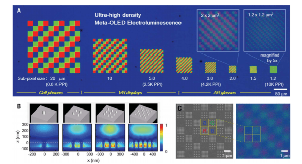
A good smartphone now will have about 500 pixels per inch (PPI) on its screen. Even the best phones we could find clock in at just over 800 PPI. But Stanford researchers have a way to make displays with more than 10,000 pixels per inch using technology borrowed from solar panel research.
Of course, that might be overkill on a six-inch phone screen, but for larger displays and close up displays like those used for virtual reality, it could be a game-changer. Your brain is good at editing it out, but in a typical VR headset, you can easily see the pixels from the display even at the highest PPI resolutions available. Worse, you can see the gaps between pixels which give a screen door-like effect. But with a density of 10,000 PPI it would be very difficult to see individual pixels, assuming you can drive that many dots.
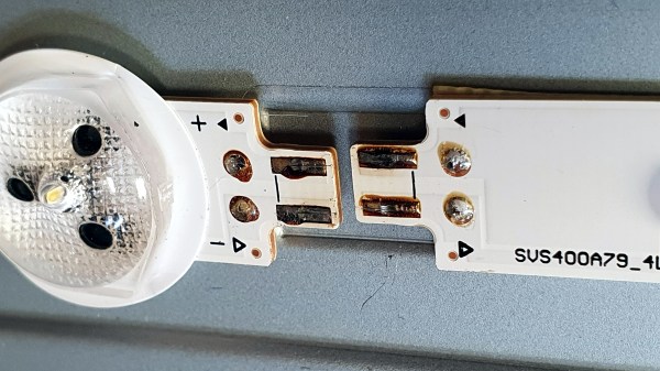
Wiggling this connector caused the backlight to turn off and on.
[Tweepy]’s TV stopped working, and the experience is a brief reminder that if a modern appliance fails, it is worth taking a look inside because the failure might be something simple. In this case, the dead TV was actually a dead LED backlight, and the fix was so embarrassingly simple that [Tweepy] is tempted to chalk it up to negligently poor DFM (design for manufacture) at best, or even some kind of effort at planned obsolescence at worst.
What happened is this: the TV appeared to stop working, but one could still make out screen content while shining a bright light on the screen. Seeing this, [Tweepy] deduced that the backlight had failed, and opened up the device to see if it could be repaired. However, the reason for the backlight failure was a surprise. It was not the power supply, nor even any of the LEDs themselves; the whole backlight wouldn’t turn on because of a cheap little PCB-to-PCB connector, and the two small spring contacts inside that had failed.
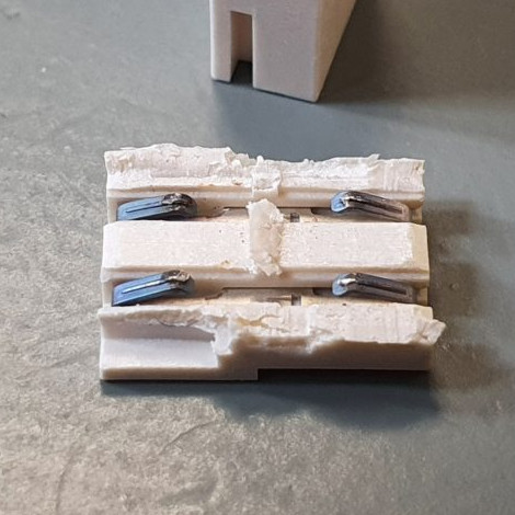
The failed connector, once cut open, showed contacts in poor condition (click to enlarge). It was ditched for a soldered connection, and the TV lived again.
From the outside things looked okay, but wiggling the connector made the backlight turn on and off, so the connection was clearly bad. Investigating further, [Tweepy] saw that the contact points of the PCBs and the two little conductors inside the connector showed clear signs of arcing and oxidation, leading to a poor connection that eventually failed, resulting in a useless TV. The fix wasn’t to clean the contacts; the correct fix was to replace the connector with a soldered connection.
Using that cheap little connector doubtlessly saved some assembly time at the factory, but it also led to failure within a fairly short amount of time. Had [Tweepy] not been handy with a screwdriver (or not bothered to investigate) the otherwise working TV would doubtlessly have ended up in a landfill.
It serves as a good reminder to make some time to investigate failures of appliances, even if one’s repair skills are limited, because the problem might be a simple one. Planned obsolescence is a tempting doorstep upon which to dump failures like this, but a good case can be made that planned obsolescence isn’t really a thing, even if manufacturers compromising products in one way or another certainly is.
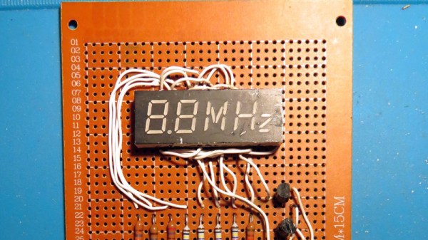
Do you know the clock speed of the computer you’re reading this article on? Maybe Hackaday readers are more likely to reply “Yes!” to that question than the general public, but if there’s a takeaway it’s that for most computer users their clock speed is now an irrelevance. It’s quick enough for the job in hand and that’s all that matters. This was not always the case though, and a few decades ago the clock speed of a PC was its major selling point. Beige boxes would have seven-segment displays lit up with the figure, and it was an unusual example of one that [Ken Yap] used to produce a clock that he believes is one-of-a-kind; unless by some slim chance somebody else has rescued the same part.
The displays were hard wired without any signals from the processor, and what makes this one unusual is that as well as having a couple of digits in yellow it also sports a segmented “MHz” in red. This would have been quite a big deal on your 486 back in about 1994. To make a clock from this unpromising start required a little creative thinking, and he manages it by using the “M” and the “H” digits to represent minutes and hours, and displaying each figure in turn. The display is wired on a piece of protoboard with an STM8 dev board, and yes, as you can see in the very short video below the break, it does tell the time.
Custom displays are more usually seen in the world of LCDs than LEDs, so this one remains a rarity on these pages. Happily there are projects out there in which people spin their own takes on the idea.
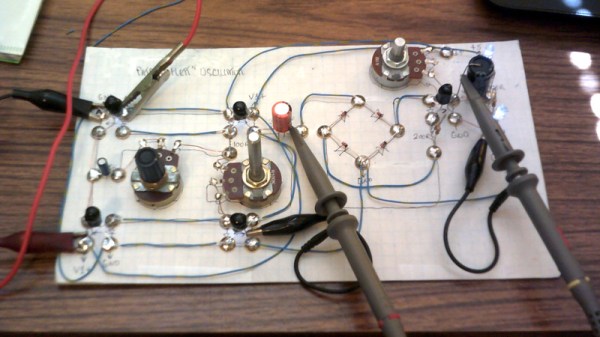
A synthesizer without transistors could almost be the basis of a trick question, surely without transistors it must be using a vacuum tube or similar. Not [Dr. Cockroach]’s synth though, instead of transistors it uses coupled pairs of LEDs and light-dependent resistors as its active components. Its oscillator circuit comes courtesy of [Patrick Flett], and uses a pair of LED/LDR combinations to alternately charge and discharge a capacitor. This feeds another LDR/LED pair that appears to act as a buffer to drive a bridge rectifier, with a final amplifier following it.
The result oscillates, though at frequencies in the low audio range with a cluster of harmonics thrown in. Its sound is best described as something akin to a small single-cylinder motorcycle engine at the lower frequencies, and is something we see could have all sorts of interesting possibilities.
This approach of using LDR-based active devices may be something of a dead end that could have had its day back in the 1930s, but it’s nevertheless an entertaining field to explore. It’s not the first time we’ve followed [Dr. Cockroach] at it, in the past we’ve seen the same technique applied to logic gates.
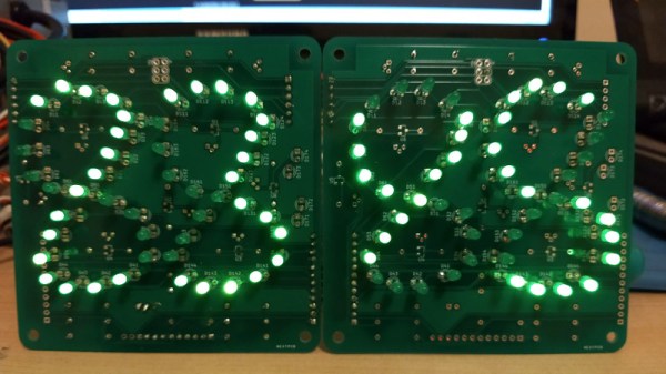
There have been many attempts at electronic numerical display technology over the decades since the first incandescent bulb or neon tube flickered into life at the command of a primordial computer, but the lowest common denominator has remained the humble seven segments. Here it might end, but for [Ken Yap] who has taken inspiration from a 1960s Sharp calculator to re-create a numerical display with only six segments.
This seemingly impossible feat is achieved by having six curved segments arranged as a figure-eight, which can render all the digits after a fashion, but which soon reveals why the extra segment made an appearance. The numbers that are made up of curves look good enough, but the straight lines in the 1, 4, and 7, are compromised by the diagonal, and the zero is curiously small at half the height. You can read the digits, but it takes getting used to.
What made sense to reduce the complexity of 1960s electronics is only a fascinating curiosity in 2020, but we maybe won’t see these displays appearing too often. You can take a look at it in the video below the break, and if you’re curious about the Sharp calculator which inspired it then you can take a look at its page in the Vintage Calculator Museum.
That is the point of [Jake Ammons’] attention-getting lighthouse, designed and built in two weeks’ time for Architectural Robotics class. It detects ambient noise and responds to it by focusing light in the direction of the sound and changing the color of the light to a significant shade to indicate different events. Up inside the lighthouse is a Teensy 4.0 to read in the sound and spin a motor in response.
[Jake]’s original directive was to make something sound-reactive, and then to turn it into an assistive device. In the future [Jake] would like to add more microphones to do sound localization. We love how sleek and professional this looks — just goes to show you what the right t-shirt stretched over 3D prints can do. Check out the demo after the break.
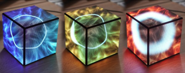
LED cubes are all the rage right now. High-end hardware capable of driving large arrays keeps getting cheaper in price, and 3D printers and pre-built boards can make assembly a snap. After attending a major hacker con and seeing the builds on display, [Sebastian] wanted a piece of the action, so set out to build his own.
While many elect to build an LED cube you can hold in your hand, [Sebastian] preferred a stationary tabletop design. This would reduce costs, allowing him to only use 3 LED boards, as the base and remaining two sides would face away from him and not be visible when placed on his desk. The 64×64 arrays are driven by an Adafruit LED matrix bonnet on top of a Raspberry Pi 2. The Pi was a tactical choice, as [Sebastian] had one lying around, and it packed enough processing power to run an OpenGL shader that creates an image for the cube that varies with the CPU load and temperature on his main desktop. As a nice final touch, the Raspberry Pi is set up to have a read-only filesystem. This allows the project to be turned off suddenly without risk of corrupting the SD card.


 That is the point of [Jake Ammons’] attention-getting lighthouse, designed and built in two weeks’ time for Architectural Robotics class. It detects ambient noise and responds to it by focusing light in the direction of the sound and changing the color of the light to a significant shade to indicate different events. Up inside the lighthouse is a Teensy 4.0 to read in the sound and spin a motor in response.