The saw in question, a Bosch EasyCut with “Nanoblade technology,” can only be defined as a chainsaw in the loosest of senses. It’s a cordless tool intended for light pruning and the like, and desperately in need of the [Tim the Toolman Taylor] treatment. The transmogrification began with a teardown of the drivetrain and addition of a custom centrifugal clutch for the 1.44-cc nitro RC car engine. The engine needed a custom base to mount it inside the case, and the original PCB made the perfect template. The original case lost a lot of weight to the bandsaw and Dremel, a cooling fan was 3D-printed, and a fascinatingly complex throttle linkage tied everything together. With a fuel tank hiding in the new 3D-printed handle, the whole thing looks like it was always supposed to have this engine. The third video below shows it in action; unfortunately, with the engine rotating the wrong direction and no room for an idler gear, [JohnnyQ90] had to settle for flipping the bar upside down to get it to cut. But with some hacks it’s the journey that interests us more than the destination.
This isn’t [JohnnyQ90]’s first nitro rodeo — he’s done nitro conversions on a cordless drill and a Dremel before. You should also check out his micro Tesla turbine, too, especially if you appreciate fine machining.
With the fine work needed for surface-mount technology, most of the job entails overcoming the limits of the human body. Eyes more than a couple of decades old need help to see what’s going on, and fingers that are fine for manipulating relatively large objects need mechanical assistance to grasp tiny SMT components. But where it can really fall apart is when you get the shakes, those involuntary tiny muscle movements that we rarely notice in the real world, but wreak havoc as we try to place components on a PCB.
To fight the shakes, you can do one of two things: remove the human, or improve the human. Unable to justify a pick and place robot for the former, [Tom] opted to build a quick hand support for surface-mount work, and the results are impressive considering it’s built entirely of scrap. It’s just a three-piece arm with standard butt hinges for joints; mounted so the hinge pins are perpendicular to the work surface and fitted with a horizontal hand rest, it constrains movement to a plane above the PCB. A hole in the hand rest for a small vacuum tip allows [Tom] to pick up a part and place it on the board — he reports that the tackiness of the solder paste is enough to remove the SMD from the tip. The video below shows it in action with decent results, but we wonder if an acrylic hand rest might provide better visibility.
Not ready for your own pick and place? That’s understandable; not every shop needs that scale of production. But we think this is a great idea for making SMT approachable to a wider audience.
Most of us are more bits-and-bytes than nuts-and-bolts, but we have the deepest appreciation for the combination of the two. So, apparently, does [rectorsquid]. Check out the design and flow of his rolling ball sculpture (YouTube, embedded below) to see what we mean. See how the arms hesitate just a bit as the ball is transferred? See how the upper arm gently places it on the ramp with a slight downward gesture? See how it’s done with one motor? There’s no way [rectorsquid] designed this on paper, right?
Of course he didn’t (YouTube). Instead, he wrote a simulator that lets him try out various custom linkages in real time. It’s a Windows-only application (sigh), but it’s free to use, while the video guides (more YouTube) look very comprehensive and give you a quick tour of the tool. Of special note is that [rectorsquid]’s software allows for sliding linkages, which he makes very good use of in the rolling ball sculpture shown here.
We’ve actually secretly featured [rectorsquid]’s Linkage software before, in this writeup of some amazing cosplay animatronic wings that used the program for their design. But we really don’t want you to miss out if you’re doing mechanical design and need something like this, or just want to play around.
Anyone know of an open-source linkage simulator that can also output STL files for 3D printing? Or in any format that could be easily transformed into OpenSCAD? Asking for a “friend”.
Electronic components are getting smaller and for most of us, our eyesight is getting worse. When [Kurt] started using a microscope to get a better view of his work, he realized he needed another tool to give his hands the same kind of precision. That tool didn’t exist so he built it.
The PantoProbe is a pantograph mechanism meant to guide a probe for reaching the tiny pads of his SMT components. He reports that he has no longer has any trouble differentiating pins 0.5 mm apart which is the diameter of the graphite sticks in our favorite mechanical pencils.
[Kurt] has already expanded his machine’s capability to include a holder for a high-frequency probe and even pulleys for a pick-and-place variation. There’s no mention of dual-wielding PantoProbes as micro-helping-hands but the versatility we’ve seen suggests that it is only a matter of time.
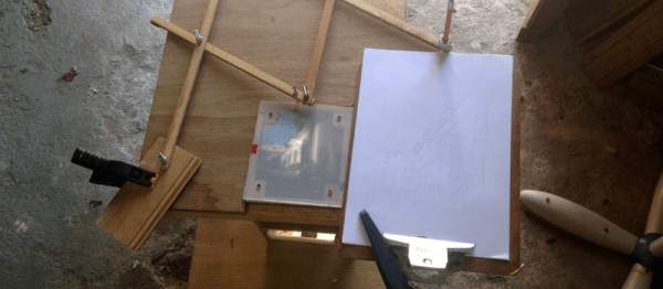
Taking a picture is as simple as tapping a screen. Drawing a memorable scene, even when it’s directly in front of you, is a different skill entirely. So trace it! Well, that’s kind of hard to do without appropriate preparation.
[bobsteaman]’s method is to first whip up a pantograph — it tested well with a felt marker on the end. Next, he built a camera obscura into a small wood box with a matte plexiglass top, which didn’t work quite so well. A magnifying glass above the camera’s pinhole aperture helped, but arduous testing was needed to ensure it was set at perfect position for a clear image. The matte plexiglass was also thrown out and, after some experimentation, replaced with a sheet of semi-transparent baking paper sandwiched between two pieces of clear plexiglass. The result is hard to argue with.
The four bar linkage is a type of mechanical linkage that is used in many different devices. A few examples are: locking pliers, bicycles, oil well pumps, loaders, internal combustion engines, compressors, and pantographs. In biology we can also find examples of this linkage, as in the human knee joint, where the mechanism allows rotation and keeps the two legs bones attached to each other. It is also present in some fish jaws that evolved to take advantage of the force multiplication that the four bar mechanism can provide.
How It Works
Deployable mirror with scissor linkages. By [Catsquisher] via Wikimedia CommonsThe study of linkages started with Archimedes who applied geometry to the study of the lever, but a full mathematical description had to wait until the late 1800’s, however, due to the complexity of the resulting equations, the study and design of complex linkages was greatly simplified with the advent of the digital computer.
Mechanical linkages in general are a group of bodies connected to each other to manage forces and movement. The bodies, or links, that form the linkage, are connected to each other at points called joints. Perhaps the simplest example is the lever, that consists of a rigid bar that is allowed to pivot about a fulcrum, used to obtain a mechanical advantage: you can raise an object using less force than the weight of the object.
Two levers can be connected to each other to form the four bar linkage. In the figure, the levers are represented by the links a (A-D) and b (B-C). The points A and B are the fulcrum points. A third link f (C-D) connects the levers, and the fourth link is the ground or frame g (A-B) where the mechanism is mounted. In the animation below, the input link a (the crank) performs a rotational motion driving the rocker rod b and resulting in a reciprocating motion of the link b (the rocker).
This slider-crank arrangement is the heart of the internal combustion engine, where the expansion of gases against a sliding piston in the cylinder drives the rotation of the crank. In a compressor the opposite happens, the rotation of the crank pushes the piston to compress the gas in the cylinder. Depending on how the mechanism is arranged, it can perform the following tasks:
convert rotational motion to reciprocating motion, as we just discussed above.
convert reciprocating motion to rotational motion, as in the bicycle.
constrain motion, e.g. knee joint and car suspension.
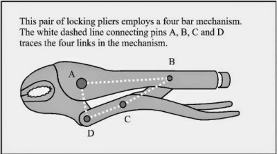
One interesting application of the four bar linkage is found in locking pliers. The B-C and C-D links are set at an angle close to 180 degrees. When force is applied to the handle, the angle between the links is less than 180 (measured from inside the linkage), and the resulting force in the jaws tries to keep the handle open. When the pliers snap into the locked position that angle becomes less than 180, and the force in the jaws keeps the handle in the locked position.
In a bicycle, the reciprocating motion of the rider´s legs is converted to rotational motion via a four bar mechanism that is formed by the two leg segments, the bicycle frame, and the crank.
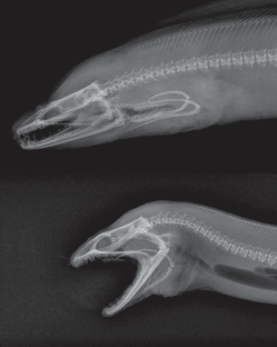
An example from nature, the Moray eel. Image from [Matthew West]As with many other inventions of humankind, we often find that nature has already come up with the same idea via evolution. The parrotfish lives on coral reefs, from which it feeds, and has to grind the coral to get to the polyps inside. For that job, they need a very powerful bite. The parrotfish obtains a mechanical advantage to the muscle force by using a four bar linkage in their jaws! Other species also use the same mechanism, one is the Moray eel, shown in the image, which has the very particular ability to launch its jaws up in the mouth to capture its prey, much like the alien from the film series.
The joints connecting the links in the linkage can be of two types. A hinged joint is called a revolute, and a sliding joint is called a prismatic. Depending on the number of revolute and prismatic joints, the four bar linkage can be of three types:
Planar quadrilateral linkage formed by four links and four revolute points. This is shown in the animation above.
Slider-crank linkage, formed by three revolute joints and a prismatic joint.
Double slider formed by two revolute joints and two prismatic joints. The Scotch yoke and the trammel of Archimedes are examples.
There are a great number of variations for the four bar linkage, and as you can guess, the design process to obtain the forces and movements that we need is not an easy task. An excellent resource for the interested reader is KMODDL (Kinematic Models for Design Digital Library) from Cornell University. Other interesting sites are the 507 mechanical movements, where you can find nice animations, and [thang010146]’s YouTube channel.
We hope to have piqued your curiosity in mechanical things. In these times of ultra fast developments in electronics, looking at the working of mechanisms that were developed centuries ago, but are still present and needed in our everyday lives can be a rewarding experience. We plan to work on more articles featuring interesting mechanisms so please let us know your favorites in the comments below.
In recent years, Cosplay as a hobby has seen improvement in the props department by leaps and bounds. Thanks in part due to the rise of the Maker culture and the easy availability of design and manufacturing tools and processes. Case in point is this awesome set of Animatronic Wings that programmer [Nelson Stoldt] built for his daughter who wanted to be Nightmare Moon.
[Nelson] had no idea what he’d gotten himself in to when he answered “Sure, I can do that”. Making motorized cosplay wings that open up to 8 feet wide and close again at the flick of a switch without weighing a ton is not a trivial project. The final rig did end up tipping the scales at just over 9 kgs, but we guess that’s a load that Cosplayers are used to hauling around.
Using a nifty program called Linkage, he played around with a few different design approaches until he found a mechanism that worked well. If you ever want to build one of [Theo Jansen]’s Strandbeest, give this program a spin. Armed with this information, and a spreadsheet to help determine the exact length of each linkage element, he modelled the project in Sketchup. The wings are operated by a scissor mechanism that is driven by a motorized screw operated sliding carriage. Wing position is measured by a potentiometer coupled to one of the wing elements. Basically, he just built a huge, powerful servo.


 In a bicycle, the reciprocating motion of the rider´s legs is converted to rotational motion via a four bar mechanism that is formed by the two leg segments, the bicycle frame, and the crank.