[Gal Pavlin] admits to enjoying the occasional dance music show. For those who have never been to one, LED one-upmanship at these shows is a real and terrible thing, so much so that an entire market exists around it. To that end, [Gal] built a pretty spiffy set of LED glasses.
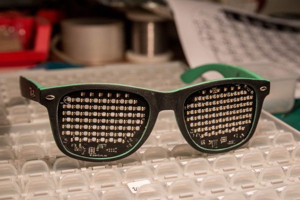
It took quite a bit of work to arrive at the final design. All the circuitry and LEDs fit entirely within the envelope of the lenses on a pair of sunglass frames of dubious parentage. The batteries squeeze in between the user’s head and temples.
On top of the clever packaging is an equally impressive set of features. Each lens is a matrix of 69 LEDs. They have an accelerometer, a microphone, and a light sensor. There’s even a vibrating alert motor, which we feel is just showing off. Best of all, you can actually see through the glasses, thanks to clever layout and very tiny LEDs.
The device requires a tag connect or soldering on a pigtail to program. If you’d like to build one yourself all the files are available on [Gavin]’s site. There’s a video of it in operation after the break.
Continue reading “LED Matrix Shades You Can Actually See Though”
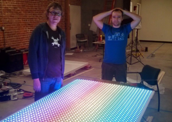
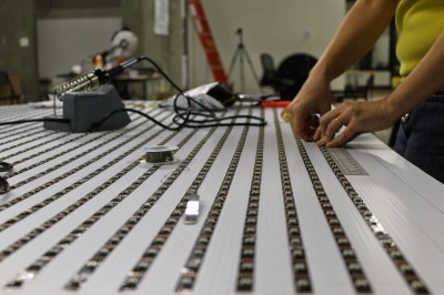 To make FLED more reliable [Ben] sourced strips of the new APA102 LEDs which