The Apple MagSafe power connector is long gone from their product line, but that doesn’t mean that magnetic connectors aren’t without their charms. It just takes the right application, and finding one might be easier with these homebrew magnetic connectors.
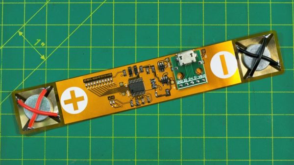
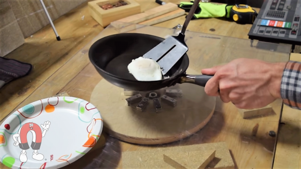
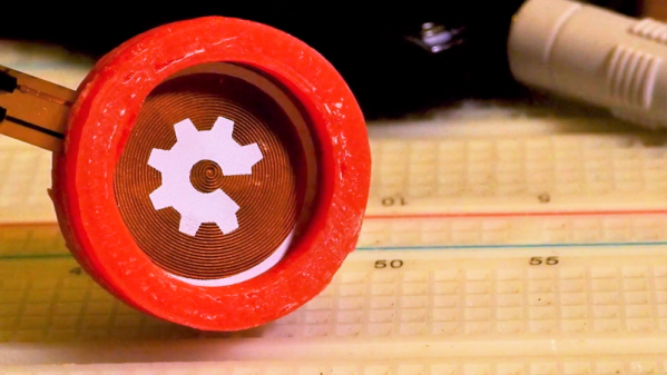
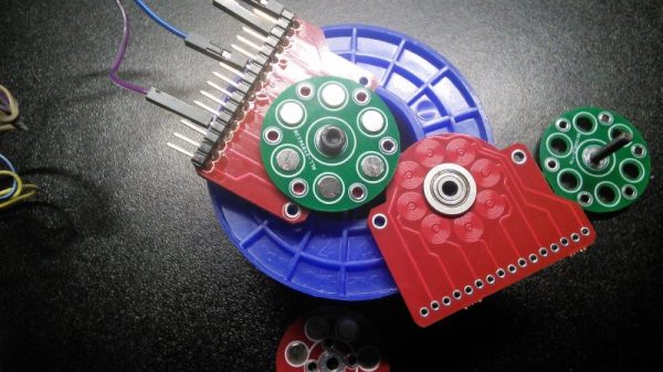
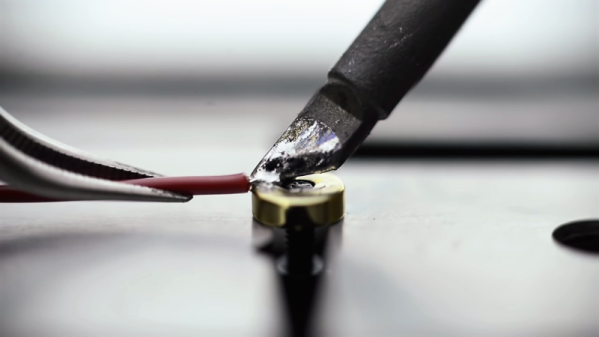
We’ll admit that the application that [Wesley Lee] found for his magnetic connectors is perhaps a little odd. He’s building something called Linobyte, a hybrid art and electronics project that pays homage to computing history with very high-style, interactive core memory modules. The connectors are for the sense wire that is weaved through the eight toroids on each module, to program it with a single byte. Each connector has a 3D-printed boot that holds a small, gold-plated neodymium magnet with the sense wire soldered to it. A socket holds another magnet to the underside of a PCB. The magnet in the boot sticks to the PCB and makes contact with pads, completing the circuit. We know what you’re thinking: heating a magnet past the Curie point is a great way to ruin it. [Wesley] admits that happens, but it just makes the connection a little weaker, which works for his application. The short video below shows how he puts them together.
We can think of a couple of ways these connectors would be useful, and we really like the look of the whole project. It’ll be interesting to see where it goes, but in the meantime, brushing up on how magnets work could be fun. Continue reading “Magnets And Printed Parts Make Quick-Disconnect Terminals”