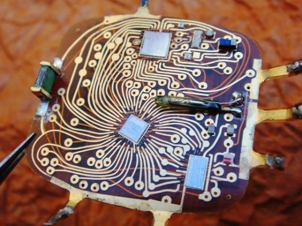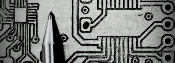
There’s an unexpected part of hacking that is very difficult to get right, namely photographing printed circuit boards. Everything seems to catch the light, making for a complex dance of manipulating light sources and camera angles. We were thus captured by [Roman Valls]’ budget rig for taking PCB photos that makes ingenious use of roadside trash to achieve a result.
It was inspired by a video featuring a much more accomplished rig, which he set out to emulate for much less outlay. Instead of an expensive lens, he’s using a Nikon camera with its kit lens. And instead of a tripod there’a a scrap drawer salvaged from the roadside and modified to become a camera holder. Lighting is diffused by baking paper, and the result is a rig that can photograph PCBs with neutral lighting and without annoying highlights.
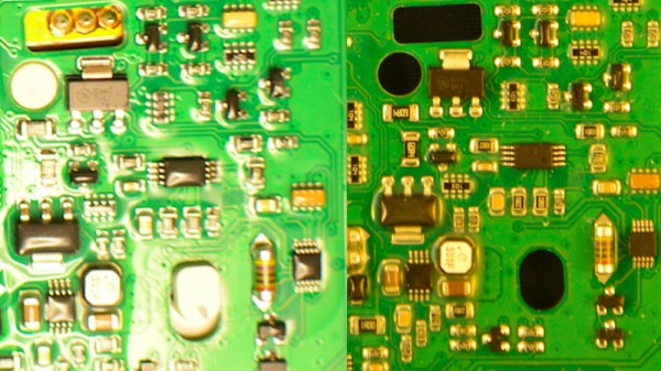
We especially like work that takes junk and makes something useful from it, and though our purpose isn’t in reverse engineering it’s impressive to see how well the technique reveals the traces. We’ll definitely be experimenting with some of the techniques herein, and those lighting tips might also work with the Hackaday ear camera microscope.